

DOI Seite / Zitierlink:
https://doi.org/10.11588/diglit.25888#0052


36
ENGINEER AND MACHINIST’S DRAWING-BOOK.
PART THIRD.
DRAWING OF MACHINERY BY ORDINARY GEOMETRICAL PROJECTION.
SECTION I.
Introductory Remarks and Definitions.
Mechanical drawing is a particular form of tlie method
of delineation generally by projection. The object of
mechanical drawing is to represent mechanical objects
upon plane surfaces. Every machine has three dimensions,
length, breadth, and thickness ; and these are susceptible
of being exactly defined. In viewing a machine from
an indefinite distance, we may suppose the rays of light
proceeding from it to move parallel to each other; and,
conceiving them to be intercepted upon a plane surface at
right angles to the rays, the representation thus formed
is said to be a projection of the machine upon that plane;
this picture or drawing will convey, so far as it goes,
correct and definite ideas of the structure and shape of
the machine. But, as the form of a machine must, in
virtue of its bulk, be referred to three series of dimensions,
each of them at right angles to the plane of the other, it
follows that any three contiguous planes of an imaginary
cubical space will answer as planes of projection. And
when we remark, further, that the component parts of
machines are, in general, disposed at right angles, it will
be seen that if the planes of the projections of a machine
be made to coincide with the disposition of its parts, its
dimensions will be represented exactly as they are: in
plainer language, there will be little or nothing of that
fore-shortening of form which necessarily occurs in repre-
sentations of natural objects, in virtue of their wavy and
ungeometrical outline.
To illustrate these remarks on geometrical projec-
tions, let us take for example a parallelopiped of which
the outlines are in bona fide planes, meeting at right
angles.
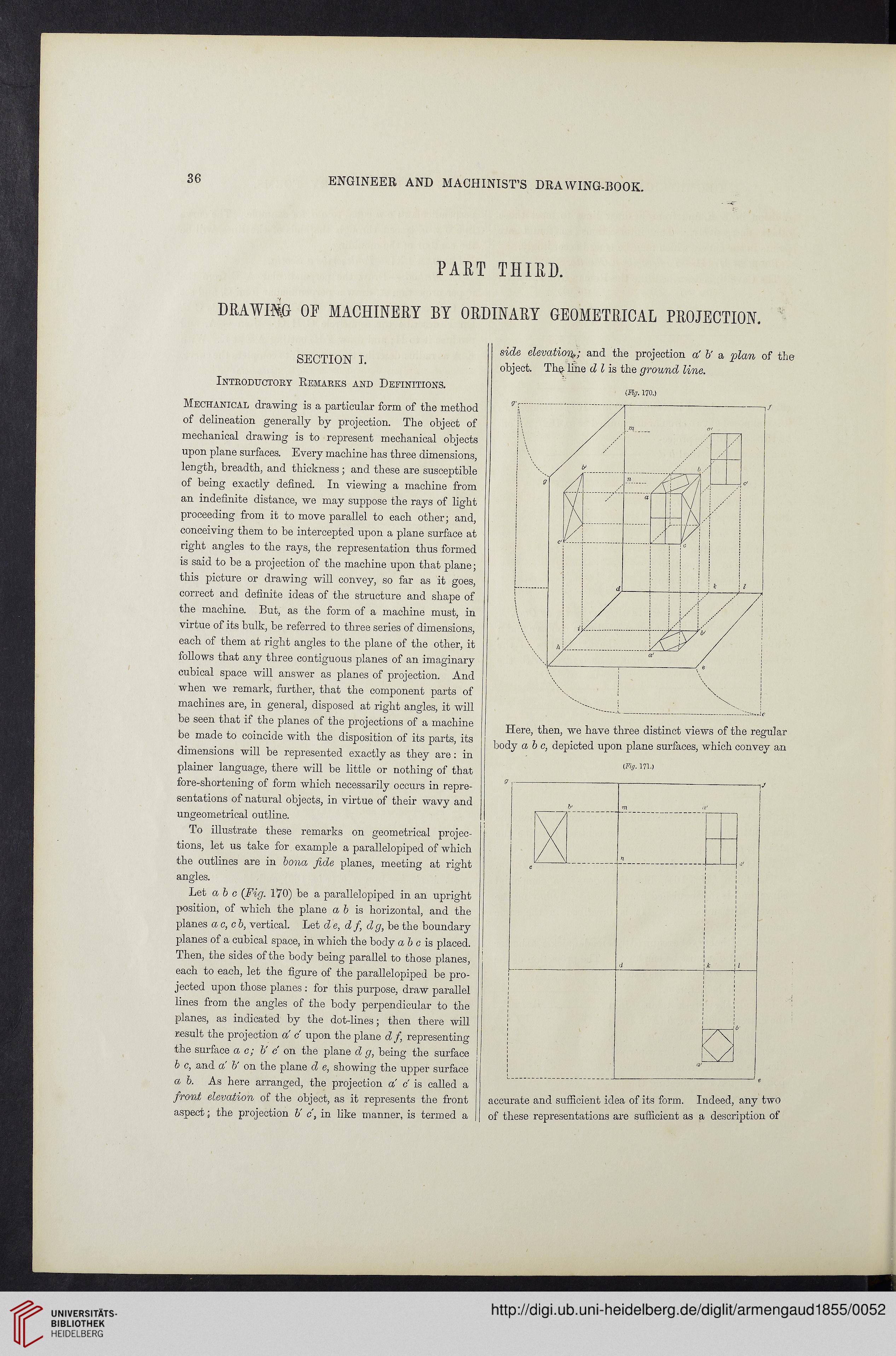
Let a b c (Fig. 170) be a parallelopiped in an upright
position, of which the plane a 6 is horizontal, and the
planes ac,cb, vertical. Let de, d fi dg, be the boundary
planes of a cubical space, in which the body a b c is placed.
Then, the sides of the body being parallel to those planes,
each to each, let the figure of the parallelopiped be pro-
jected upon those planes: for this purpose, draw parallel
lines from the angles of the body perpendicular to the
planes, as indicated by the dot-lines; then there mil
result the projection a c upon the plane df, representing
the surface a c; b' c on the plane d g, being the surface
b c, and a b' on the plane d e, showing the upper surface
a b. As here arranged, the projection a c is called a
front elevation of the object, as it represents the front
aspect; the projection b' c, in like manner, is termed a
side elevationi,; and the projection a' b' a plan of the
object. The line d l is the ground line.
<%. 170.)
ENGINEER AND MACHINIST’S DRAWING-BOOK.
PART THIRD.
DRAWING OF MACHINERY BY ORDINARY GEOMETRICAL PROJECTION.
SECTION I.
Introductory Remarks and Definitions.
Mechanical drawing is a particular form of tlie method
of delineation generally by projection. The object of
mechanical drawing is to represent mechanical objects
upon plane surfaces. Every machine has three dimensions,
length, breadth, and thickness ; and these are susceptible
of being exactly defined. In viewing a machine from
an indefinite distance, we may suppose the rays of light
proceeding from it to move parallel to each other; and,
conceiving them to be intercepted upon a plane surface at
right angles to the rays, the representation thus formed
is said to be a projection of the machine upon that plane;
this picture or drawing will convey, so far as it goes,
correct and definite ideas of the structure and shape of
the machine. But, as the form of a machine must, in
virtue of its bulk, be referred to three series of dimensions,
each of them at right angles to the plane of the other, it
follows that any three contiguous planes of an imaginary
cubical space will answer as planes of projection. And
when we remark, further, that the component parts of
machines are, in general, disposed at right angles, it will
be seen that if the planes of the projections of a machine
be made to coincide with the disposition of its parts, its
dimensions will be represented exactly as they are: in
plainer language, there will be little or nothing of that
fore-shortening of form which necessarily occurs in repre-
sentations of natural objects, in virtue of their wavy and
ungeometrical outline.
To illustrate these remarks on geometrical projec-
tions, let us take for example a parallelopiped of which
the outlines are in bona fide planes, meeting at right
angles.
Let a b c (Fig. 170) be a parallelopiped in an upright
position, of which the plane a 6 is horizontal, and the
planes ac,cb, vertical. Let de, d fi dg, be the boundary
planes of a cubical space, in which the body a b c is placed.
Then, the sides of the body being parallel to those planes,
each to each, let the figure of the parallelopiped be pro-
jected upon those planes: for this purpose, draw parallel
lines from the angles of the body perpendicular to the
planes, as indicated by the dot-lines; then there mil
result the projection a c upon the plane df, representing
the surface a c; b' c on the plane d g, being the surface
b c, and a b' on the plane d e, showing the upper surface
a b. As here arranged, the projection a c is called a
front elevation of the object, as it represents the front
aspect; the projection b' c, in like manner, is termed a
side elevationi,; and the projection a' b' a plan of the
object. The line d l is the ground line.
<%. 170.)