

DOI Seite / Zitierlink:
https://doi.org/10.11588/diglit.25888#0054


38
ENGINEER AND MACHINIST’S DRAWING-BOOK.
use on a convenient spare part of the sheet. To do so, all
that is necessary is to draw a line, and set off upon it a
convenient number of “ feet ” of the scale, and to divide
one of these feet at either end into inches, and divide still
further, if thought necessary, into parts of an inch. The
feet should be numbered for easy reference.
A rough estimate should be formed of the space which
the drawing will occupy, whether in one or more views.
For this purpose, it is sufficient to take the extreme dimen-
sions of the machine in the planes in which it is to be drawn;
and thus the positions of the several views may be arranged
beforehand. In general, where one or two elevations and
a plan are to be drawn, the elevations are drawn first, as
they usually convey a more complete idea of the machine,
and the dimensions may readily be transferred to the plan.
Of two elevations, end and side, the side elevation is usu-
ally first prepared, as it generally exhibits a greater num-
ber of parts than the other. Again, the plan may be first
made, when any geometrical operations are necessary
towards the forming of the elevation. Indeed, it is some-
times better to prepare two or three views conjointly, when
the progress of the whole drawing can be facilitated.
SECTION III.
Of Shade Lines.
Shade or shadow lines act an important part in outline
drawings, or drawings which consist simply of the lines
employed to indicate the form of the object represented.
The appearance of the object, due to the variety of light
and shade with which it is natu-
rally invested, is not recognized in
outline drawings: for example, the
roundness, the flatness, or the obli-
quity of individual surfaces, is not
indicated by the mere lines which
tell of their form, although it may
generally be inferred from the rela-
tion of different views of the same
part. To understand an outline
drawing, the exercise of judgment
is necessary in connection with a
knowledge of the general rules of
mechanical construction in detail.
The direct significance of an outline
drawing may, however, be con-
siderably increased, by strengthen- tFir>-173-)
ing those lines which indicate the contours of surfaces
resting in the shadow ; and this distinction also improves
the general appearance of the drawing. The strong lines,
to produce the best effect, ought to be laid upon the sharp
edges at the summits of salient angles. It is inelegant
and improper to strengthen in any marked degree such
lines as usually indicate the limits of rounded surfaces, as
these are only apparent, not real contours, due to the cur-
vature of the surface and the particular point from which
they are viewed. For example, a sphere, from any point
of view, is represented by a circle. There is an obvious
necessity for such a line to represent the form of the object,
though the proper office of lines is to represent the inter-
sections of surfaces; while the surface of a sphere is a
uniform curve. Bounding lines for curve surfaces should,
then, be drawn finely, and should be but slightly, if at all,
strengthened on the shade side. This distinction assists
in contrasting flat and curve surfaces. To understand and
apply the shade-lines, however, we must know the direc-
tion in which the light is supposed to fall upon the
object, and thence the locality of the shadows. The in-
vestigation of this subject in detail is reserved for future
treatment; meantime, it will be explained so far as it
applies to the finishing of outline drawings.
It is necessary, for the explicitness of the drawing, that,
in the first place, the light be supposed to fall upon the
object in parallel lines, that all the parts may be shade-
lined according to one uniform rule; secondly, that the
light should be supposed to fall upon the object, neither
vertically nor horizontally, but obliquely, as in this way,
both the horizontal and vertical lines may be relieved by
shading. To distribute the shadows equally, the light is
supposed to fall in directions forming an angle of 45° with
both the horizontal and the vertical planes of projection.
In short, for elevations, the light should fall, as it were,
from towards the upper left hand corner of the sheet of
paper, supposing it square, making also an angle of 45°
with the surface ; and for plans, other circumstances being
the same, it should proceed from the lower left hand corner.
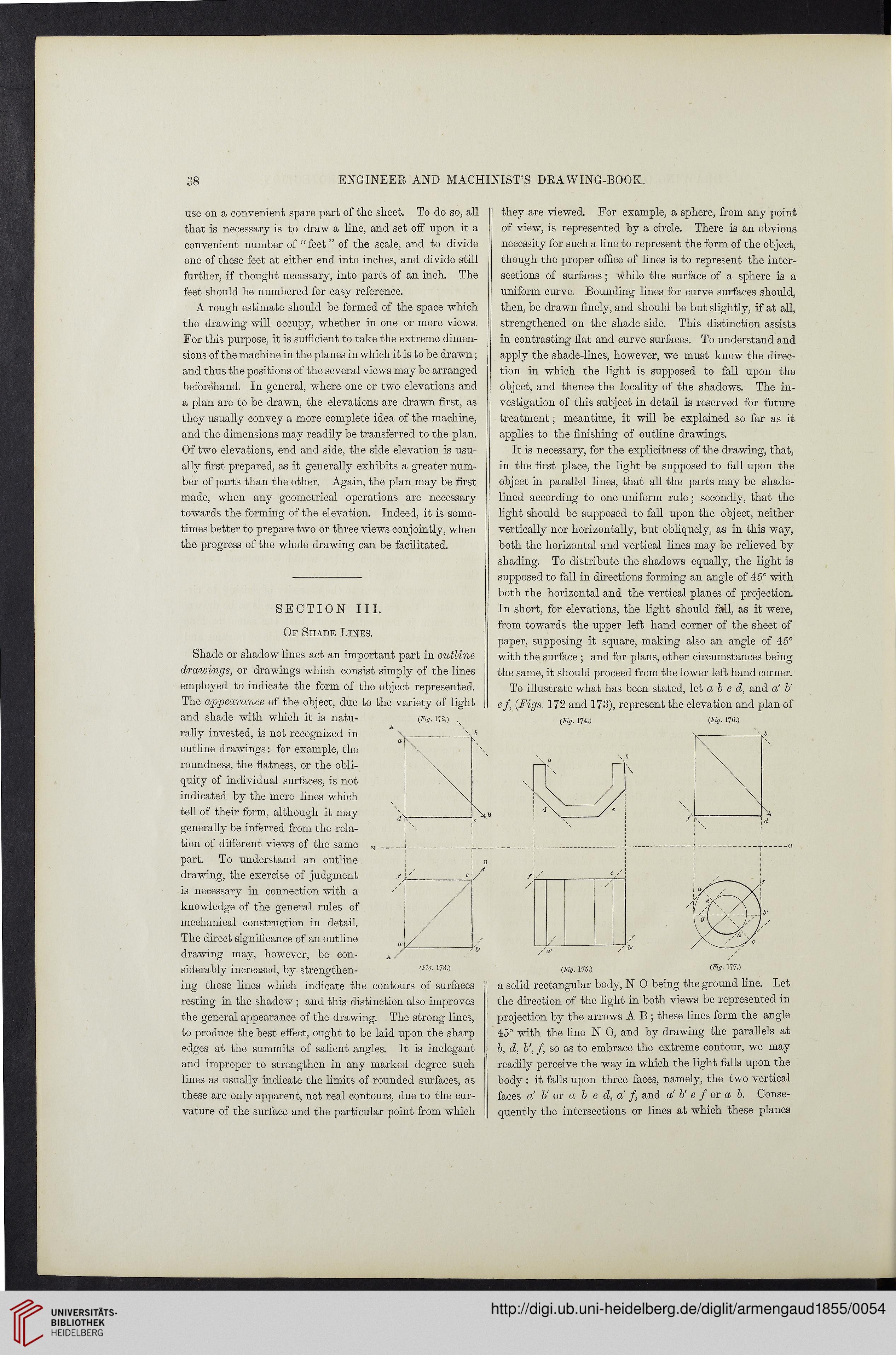
To illustrate what has been stated, let a b c d, and a' b'
e/, {Figs. 172 and 173), represent the elevation and plan of
(Fig. 175.) (FiS-177-)
a solid rectangular body, N 0 being the ground fine. Let
the direction of the light in both views be represented in
projection by the arrows A B ; these lines form the angle
45° with the line N 0, and by drawing the parallels at
b, d, b', /, so as to embrace the extreme contour, we may
readily perceive the way in which the light falls upon the
body : it falls upon three faces, namely, the two vertical
faces a' V or a b c d, a' /, and a! b' e f or a b. Conse-
quently the intersections or lines at which these planes
ENGINEER AND MACHINIST’S DRAWING-BOOK.
use on a convenient spare part of the sheet. To do so, all
that is necessary is to draw a line, and set off upon it a
convenient number of “ feet ” of the scale, and to divide
one of these feet at either end into inches, and divide still
further, if thought necessary, into parts of an inch. The
feet should be numbered for easy reference.
A rough estimate should be formed of the space which
the drawing will occupy, whether in one or more views.
For this purpose, it is sufficient to take the extreme dimen-
sions of the machine in the planes in which it is to be drawn;
and thus the positions of the several views may be arranged
beforehand. In general, where one or two elevations and
a plan are to be drawn, the elevations are drawn first, as
they usually convey a more complete idea of the machine,
and the dimensions may readily be transferred to the plan.
Of two elevations, end and side, the side elevation is usu-
ally first prepared, as it generally exhibits a greater num-
ber of parts than the other. Again, the plan may be first
made, when any geometrical operations are necessary
towards the forming of the elevation. Indeed, it is some-
times better to prepare two or three views conjointly, when
the progress of the whole drawing can be facilitated.
SECTION III.
Of Shade Lines.
Shade or shadow lines act an important part in outline
drawings, or drawings which consist simply of the lines
employed to indicate the form of the object represented.
The appearance of the object, due to the variety of light
and shade with which it is natu-
rally invested, is not recognized in
outline drawings: for example, the
roundness, the flatness, or the obli-
quity of individual surfaces, is not
indicated by the mere lines which
tell of their form, although it may
generally be inferred from the rela-
tion of different views of the same
part. To understand an outline
drawing, the exercise of judgment
is necessary in connection with a
knowledge of the general rules of
mechanical construction in detail.
The direct significance of an outline
drawing may, however, be con-
siderably increased, by strengthen- tFir>-173-)
ing those lines which indicate the contours of surfaces
resting in the shadow ; and this distinction also improves
the general appearance of the drawing. The strong lines,
to produce the best effect, ought to be laid upon the sharp
edges at the summits of salient angles. It is inelegant
and improper to strengthen in any marked degree such
lines as usually indicate the limits of rounded surfaces, as
these are only apparent, not real contours, due to the cur-
vature of the surface and the particular point from which
they are viewed. For example, a sphere, from any point
of view, is represented by a circle. There is an obvious
necessity for such a line to represent the form of the object,
though the proper office of lines is to represent the inter-
sections of surfaces; while the surface of a sphere is a
uniform curve. Bounding lines for curve surfaces should,
then, be drawn finely, and should be but slightly, if at all,
strengthened on the shade side. This distinction assists
in contrasting flat and curve surfaces. To understand and
apply the shade-lines, however, we must know the direc-
tion in which the light is supposed to fall upon the
object, and thence the locality of the shadows. The in-
vestigation of this subject in detail is reserved for future
treatment; meantime, it will be explained so far as it
applies to the finishing of outline drawings.
It is necessary, for the explicitness of the drawing, that,
in the first place, the light be supposed to fall upon the
object in parallel lines, that all the parts may be shade-
lined according to one uniform rule; secondly, that the
light should be supposed to fall upon the object, neither
vertically nor horizontally, but obliquely, as in this way,
both the horizontal and vertical lines may be relieved by
shading. To distribute the shadows equally, the light is
supposed to fall in directions forming an angle of 45° with
both the horizontal and the vertical planes of projection.
In short, for elevations, the light should fall, as it were,
from towards the upper left hand corner of the sheet of
paper, supposing it square, making also an angle of 45°
with the surface ; and for plans, other circumstances being
the same, it should proceed from the lower left hand corner.
To illustrate what has been stated, let a b c d, and a' b'
e/, {Figs. 172 and 173), represent the elevation and plan of
(Fig. 175.) (FiS-177-)
a solid rectangular body, N 0 being the ground fine. Let
the direction of the light in both views be represented in
projection by the arrows A B ; these lines form the angle
45° with the line N 0, and by drawing the parallels at
b, d, b', /, so as to embrace the extreme contour, we may
readily perceive the way in which the light falls upon the
body : it falls upon three faces, namely, the two vertical
faces a' V or a b c d, a' /, and a! b' e f or a b. Conse-
quently the intersections or lines at which these planes