

DOI Seite / Zitierlink:
https://doi.org/10.11588/diglit.25888#0128


112
THE ENGINEER AND MACHINIST’S DRAWING-BOOK.
ence. In the horizontal wheel the centre lines and the
width of the roots of the teeth are drawn on the plan,
and visual rays drawn from these, give the divisions on
the picture-line, from which perpendiculars are drawn
to intersect the middle perspective circle. The visual
rays of the centres of the teeth, and their corresponding
perpendiculars only, are shown. The hither ends of the
teeth may be sketched in; but if the student cannot do
this properly, it will be necessary to draw the lines bound-
ing the upper surfaces of the teeth, all on the plan; and
by visual rays to find their perspective widths in the same
way as the widths of their roots.
The divisions of the teeth of the vertical wheels are
drawn by another method, which, as we have said, is
equally applicable to that of the horizontal wheel. The
line F F on the ground plan of the right hand vertical
bevel-wheel, is also the horizontal projection of the side of
its circumscribing square. This line intersects the picture-
line at the mark X. and consequently if a perpendicular be
drawn from x, and transferred to the perspective ground-
line, and the divisions of the teeth taken on a correspond-
ing vertical line on the geometrical drawing are set up
on this, then lines from these divisions drawn to the
right hand vanishing point will intersect the perspective
circle, and will give the divisions on it. In this, as in the
horizontal wheel, the centres of the teeth only are shown,
and the remark as to the means of completing the repre-
sentation of the teeth of the horizontal wheels, applies
equally to the completion of the representation of the teeth
in the vertical wheel. The teeth of the left hand vertical
wheel are formed by drawing from the divisions of the
right hand wheel, lines to the left hand vanishing point, to
intersect the perspective circles of the left hand wheel.
Part of the shaft, with its clutch and handle, are also
shown in this drawing.
Plate 70, figs. 4 A and 4 B (Perspective Lesson, Part
Fourth). To the plan are now added the details of the
clutch and the ribs, and other details of the wheels. The
circles of the clutch are obtained in the same manner as
the circles of the wheels. The ribs of the horizontal
wheel may be obtained by producing the original lines on
the plan, to meet the picture-line, as at G G, and trans-
ferring them to the perspective at g g, and finding the per-
spective of the square which their intersection forms at li h.
It may be almost unnecessary to repeat that the circles of
the shafts, and annular openings in the faces of the wheels,
are obtained from their circumscribing squares.
Plate 71, figs. 5 A and 5 B (Perspective Lesson, Part
Fifth). The plumber-blocks are now added to the plan.
All the directions necessary for finding the perspectives of
any points have been given in the previous stages of this
lesson, and if the student has carefully followed the pro-
cess, he will have no difficulty in finding the perspectives
of the plumber-blocks, and consequently completing the
entire figure. The pencil lines of construction being obli-
terated, we have a perfect perspective representation in
outline; and the figure thus completed, is given, fully
shaded, in the engraved title to the work.
SECTION II.
Isometric Projection.
This is a conventional manner of representing an object,
in which it has somewhat the appearance of a perspective
drawing, with the advantage of the lines situated in the
three visible planes at right angles to each other, retain-
ing their exact dimensions. For the representation of
such objects, therefore, as have their principal parts in
planes at right angles to each other, this kind of projection
is particularly well adapted. The name isometrical was
given to this projection by Professor Farish, of Cambridge.
The principle of isometric representation consists in
selecting for the plane of the projection, one equally in-
clined to three principal axes, at right angles to each
other, so that all straight lines coincident with or parallel
to these axes, are drawn in projection to the same scale.
The axes are called isometric axes, and all lines parallel to
them are called isometric lines. The planes containing
the isometric axes are isometric planes; the point in the
object projected, assumed as the origin of the axes, is
called the regulating point.
(Fig. 23i.) If any 0f flie solid angles of a
cube (Fig. 231) be made the regulat-
ing point, and the three lines which
meet in it the isometric axes, then
it may be demonstrated, that the
plane of projection to be such that
these axes will make equal angles
with it, must be at right angles to
that diagonal of the cube which
passes through the regulating point.
The projection of the cube will therefore be as A B C D
E F G in the figure.
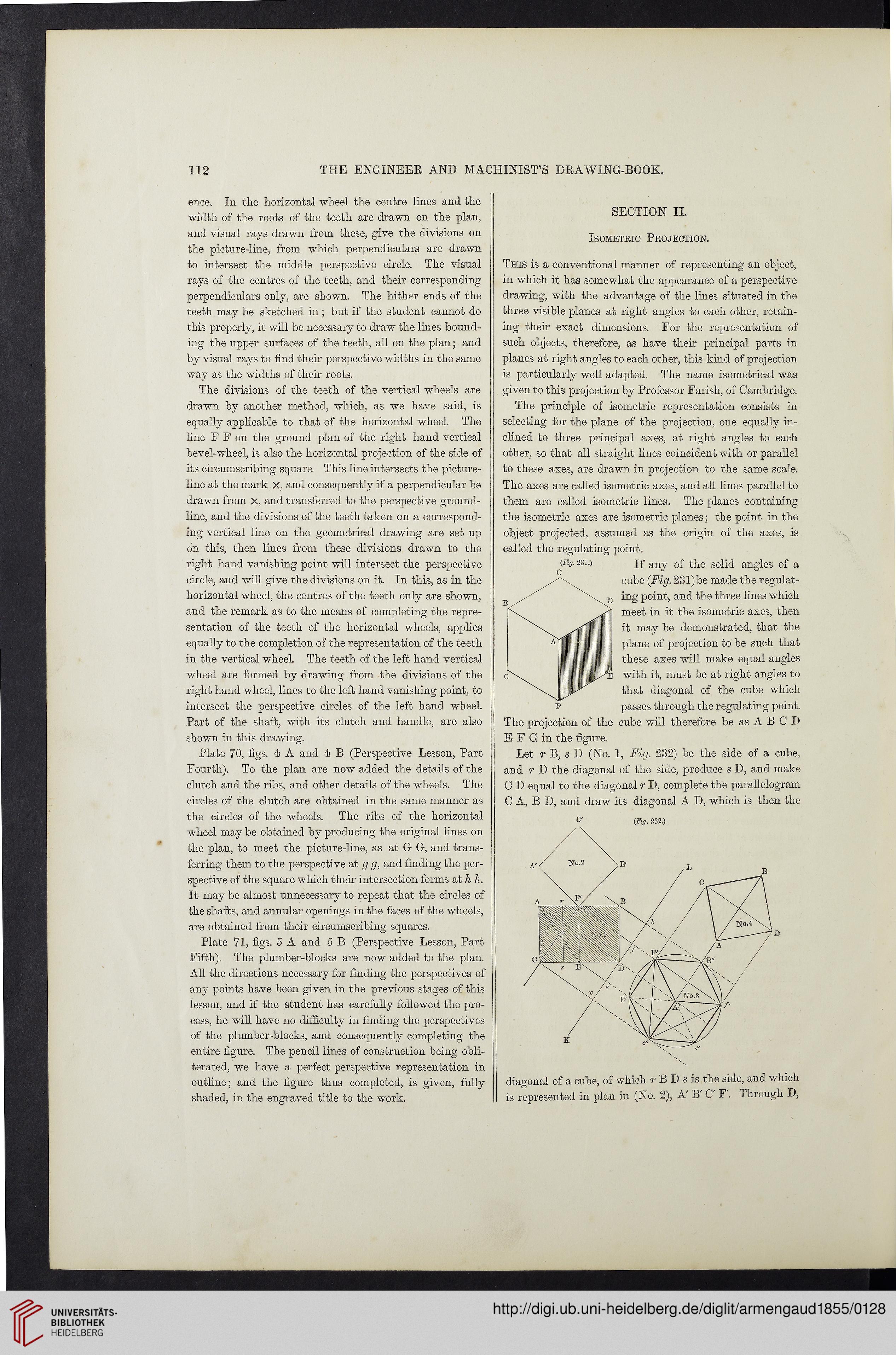
Let r B, s D (No. 1, Fig. 232) be the side of a cube,
and r D the diagonal of the side, produce s D, and make
C D equal to the diagonal r D, complete the parallelogram
C A, B D, and draw its diagonal A D, which is then the
(Fig. 232.)
.agonal of a cube, of which r B D s is the side, and which
represented in plan in (No. 2), A'B C F. Through D,
THE ENGINEER AND MACHINIST’S DRAWING-BOOK.
ence. In the horizontal wheel the centre lines and the
width of the roots of the teeth are drawn on the plan,
and visual rays drawn from these, give the divisions on
the picture-line, from which perpendiculars are drawn
to intersect the middle perspective circle. The visual
rays of the centres of the teeth, and their corresponding
perpendiculars only, are shown. The hither ends of the
teeth may be sketched in; but if the student cannot do
this properly, it will be necessary to draw the lines bound-
ing the upper surfaces of the teeth, all on the plan; and
by visual rays to find their perspective widths in the same
way as the widths of their roots.
The divisions of the teeth of the vertical wheels are
drawn by another method, which, as we have said, is
equally applicable to that of the horizontal wheel. The
line F F on the ground plan of the right hand vertical
bevel-wheel, is also the horizontal projection of the side of
its circumscribing square. This line intersects the picture-
line at the mark X. and consequently if a perpendicular be
drawn from x, and transferred to the perspective ground-
line, and the divisions of the teeth taken on a correspond-
ing vertical line on the geometrical drawing are set up
on this, then lines from these divisions drawn to the
right hand vanishing point will intersect the perspective
circle, and will give the divisions on it. In this, as in the
horizontal wheel, the centres of the teeth only are shown,
and the remark as to the means of completing the repre-
sentation of the teeth of the horizontal wheels, applies
equally to the completion of the representation of the teeth
in the vertical wheel. The teeth of the left hand vertical
wheel are formed by drawing from the divisions of the
right hand wheel, lines to the left hand vanishing point, to
intersect the perspective circles of the left hand wheel.
Part of the shaft, with its clutch and handle, are also
shown in this drawing.
Plate 70, figs. 4 A and 4 B (Perspective Lesson, Part
Fourth). To the plan are now added the details of the
clutch and the ribs, and other details of the wheels. The
circles of the clutch are obtained in the same manner as
the circles of the wheels. The ribs of the horizontal
wheel may be obtained by producing the original lines on
the plan, to meet the picture-line, as at G G, and trans-
ferring them to the perspective at g g, and finding the per-
spective of the square which their intersection forms at li h.
It may be almost unnecessary to repeat that the circles of
the shafts, and annular openings in the faces of the wheels,
are obtained from their circumscribing squares.
Plate 71, figs. 5 A and 5 B (Perspective Lesson, Part
Fifth). The plumber-blocks are now added to the plan.
All the directions necessary for finding the perspectives of
any points have been given in the previous stages of this
lesson, and if the student has carefully followed the pro-
cess, he will have no difficulty in finding the perspectives
of the plumber-blocks, and consequently completing the
entire figure. The pencil lines of construction being obli-
terated, we have a perfect perspective representation in
outline; and the figure thus completed, is given, fully
shaded, in the engraved title to the work.
SECTION II.
Isometric Projection.
This is a conventional manner of representing an object,
in which it has somewhat the appearance of a perspective
drawing, with the advantage of the lines situated in the
three visible planes at right angles to each other, retain-
ing their exact dimensions. For the representation of
such objects, therefore, as have their principal parts in
planes at right angles to each other, this kind of projection
is particularly well adapted. The name isometrical was
given to this projection by Professor Farish, of Cambridge.
The principle of isometric representation consists in
selecting for the plane of the projection, one equally in-
clined to three principal axes, at right angles to each
other, so that all straight lines coincident with or parallel
to these axes, are drawn in projection to the same scale.
The axes are called isometric axes, and all lines parallel to
them are called isometric lines. The planes containing
the isometric axes are isometric planes; the point in the
object projected, assumed as the origin of the axes, is
called the regulating point.
(Fig. 23i.) If any 0f flie solid angles of a
cube (Fig. 231) be made the regulat-
ing point, and the three lines which
meet in it the isometric axes, then
it may be demonstrated, that the
plane of projection to be such that
these axes will make equal angles
with it, must be at right angles to
that diagonal of the cube which
passes through the regulating point.
The projection of the cube will therefore be as A B C D
E F G in the figure.
Let r B, s D (No. 1, Fig. 232) be the side of a cube,
and r D the diagonal of the side, produce s D, and make
C D equal to the diagonal r D, complete the parallelogram
C A, B D, and draw its diagonal A D, which is then the
(Fig. 232.)
.agonal of a cube, of which r B D s is the side, and which
represented in plan in (No. 2), A'B C F. Through D,