

DOI Seite / Zitierlink:
https://doi.org/10.11588/diglit.25888#0021


CONSTRUCTION AND USE OF DRAWING INSTRUMENTS.
5
of equal parts, D E will be the side of another square of
one-third the area. And if any number be brought to the
index, and the same number be taken by A B from a scale
of equal parts, D E will be the square-root of that number.
And in this latter case, D E will also be a mean propor-
tional between any two numbers, whose product is equal
to A B.
The line of solids expresses the proportion between cubes
and spheres. Thus, if the index be set at 2, and the dia-
meter of a sphere, or the side of a cube, be taken from a
scale of equal parts by A B, then will D E be a diameter
or side of a sphere or cube of half the solidity. And if the
slide be set to (say) 8, and the same number be taken from
a scale of equal parts, then will D E measure 2 on the same
scale, or the cube-root of 8.
The scale of lines and that of circles are those of most
value to the draughtsman. The first enables him to reduce
or enlarge in any required proportion ; and the second
gives him the side of the square or polygon, that can be
inscribed in a given circle. The instrument needs to be
used carefully, since its accuracy depends on the preser-
vation of the points. If both or either of these are broken,
or diminished in length, the proportions cease to be true.
In place of using the proportional compasses in setting off
a number of times, which would soon wear the points,
rather take the distance in the Dividers.
Beam Compasses. — The engineer has frequently to
measure and lay down distances, and to sweep with x’adii,
which the ordinaiy instruments cannot reach. In these
cases, and when extreme accuracy is necessary, he resorts
to the Beam Compasses, which are usually made of well-
seasoned mahogany, with a slip of holly or box-wood on
the face, to carry the scale. Two brass boxes with points
are fitted to the beam, one of which moves freely to take
in any required distance, and the other is connected with
a slow-motion screw working in the end of the beam, and
can thus be adjusted with extreme delicacy to any measure
or radius. Reading-plates, on the vernier principle, sub-
divide the divisions of the scale on the beam, and by them
any measure of three places of figures is taken with extreme
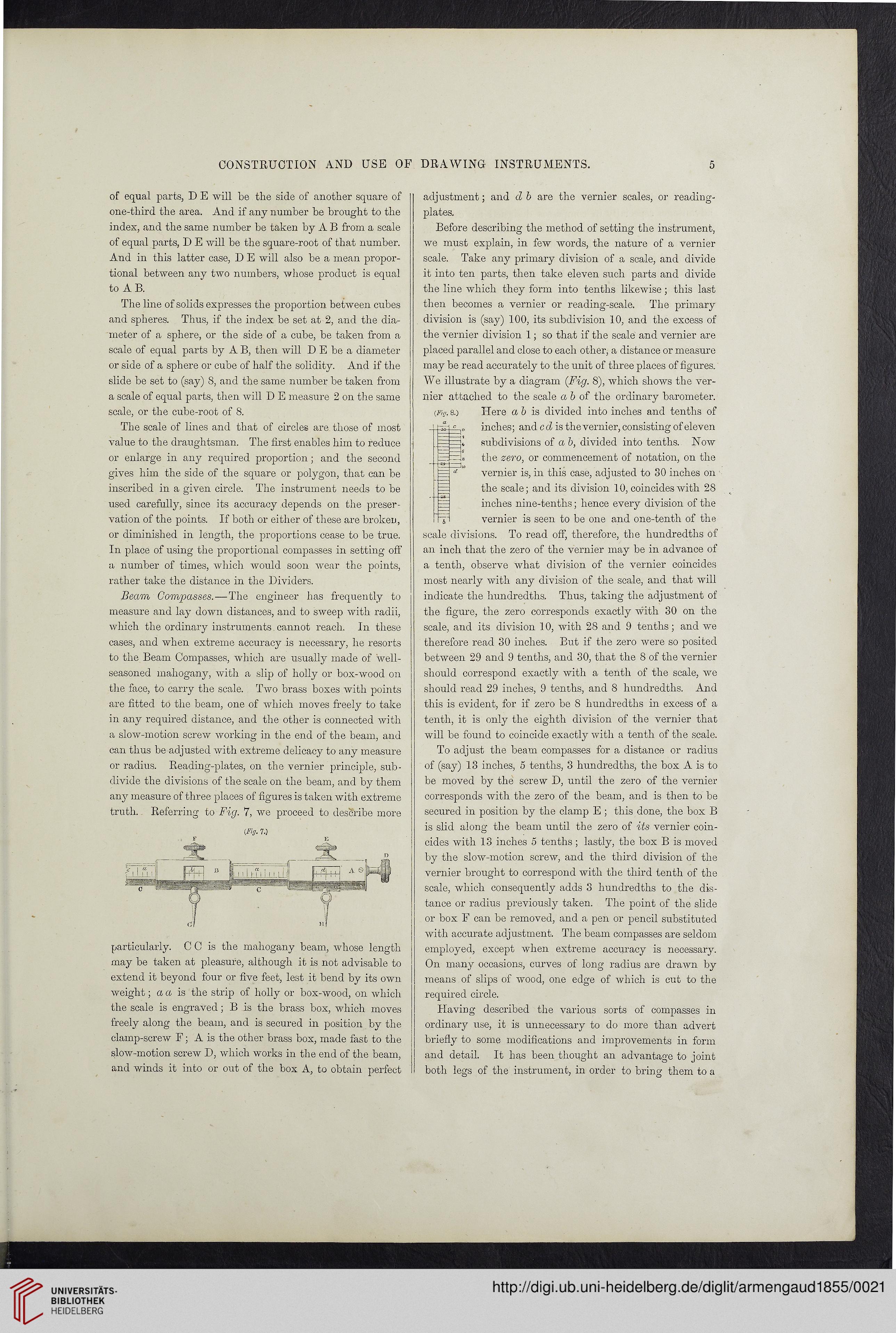
truth. Referring to Fig. 7, we proceed to describe more
{Fig. 7.)
particularly. C C is the mahogany beam, whose length i
may be taken at pleasure, although it is not advisable to
extend it beyond four or five feet, lest it bend by its own
weight; a a is the strip of holly or box-wood, on which
the scale is engraved; B is the brass box, which moves
freely along the beam, and is secured in position by the
clamp-screw F; A is the other brass box, made fast to the
slow-motion screw D, which works in the end of the beam,
and winds it into or out of the box A, to obtain perfect
adjustment; and d b are the vernier scales, or reading-
plates.
Before describing the method of setting the instrument,
we must explain, in few words, the nature of a vernier
scale. Take any primary division of a scale, and divide
it into ten parts, then take eleven such parts and divide
the line which they form into tenths likewise; this last
then becomes a vernier or reading-scale. The primary
division is (say) 100, its subdivision 10, and the excess of
the vernier division 1; so that if the scale and vernier are
placed parallel and close to each other, a distance or measure
may be read accurately to the unit of three places of figures.
We illustrate by a diagram (Fig. 8), which shows the ver-
nier attached to the scale ab of the ordinary barometer.
Here a b is divided into inches and tenths of
inches; and c d is the vernier, consisting of eleven
subdivisions of a b, divided into tenths. Now
the zero, or commencement of notation, on the
vernier is, in this case, adjusted to 80 inches on
the scale; and its division 10, coincides with 28
inches nine-tenths; hence every division of the
vernier is seen to be one and one-tenth of the
scale divisions. To read off, therefore, the hundredths ot
an inch that the zero of the vernier may be in advance of
a tenth, observe what division of the vernier coincides
most nearly with any division of the scale, and that will
indicate the hundredths. Thus, taking the adjustment of
the figure, the zero corresponds exactly with 30 on the
scale, and its division 10, with 28 and 9 tenths; and we
therefore read 30 inches. But if the zero were so posited
between 29 and 9 tenths, and 30, that the 8 of the vernier
should correspond exactly with a tenth of the scale, we
should read 29 inches, 9 tenths, and 8 hundredths. And
this is evident, for if zero be 8 hundredths in excess of a
tenth, it is only the eighth division of the vernier that
will be found to coincide exactly with a tenth of the scale.
To adjust the beam compasses for a distance or radius
of (say) 13 inches, 5 tenths, 3 hundredths, the box A is to
be moved by the screw D, until the zero of the vernier
corresponds with the zero of the beam, and is then to be
secured in position by the clamp E ; this done, the box B
is slid along the beam until the zero of its vernier coin-
cides with 13 inches 5 tenths; lastly, the box B is moved
by the slow-motion screw, and the third division of the
vernier brought to correspond with the third tenth of the
scale, which consequently adds 3 hundredths to the dis-
tance or radius previously taken. The point of the slide
or box F can be removed, and a pen or pencil substituted
with accurate adjustment. The beam compasses are seldom
employed, except when extreme accuracy is necessary.
On many occasions, curves of long radius are drawn by
means of slips of wood, one edge of which is cut to the
required circle.
Having described the various sorts of compasses in
ordinary use, it is unnecessary to do more than advert
briefly to some modifications and improvements in form
and detail. It has been thought an advantage to joint
both legs of the instrument, in order to bring them to a
(Fio, 8.)
5
of equal parts, D E will be the side of another square of
one-third the area. And if any number be brought to the
index, and the same number be taken by A B from a scale
of equal parts, D E will be the square-root of that number.
And in this latter case, D E will also be a mean propor-
tional between any two numbers, whose product is equal
to A B.
The line of solids expresses the proportion between cubes
and spheres. Thus, if the index be set at 2, and the dia-
meter of a sphere, or the side of a cube, be taken from a
scale of equal parts by A B, then will D E be a diameter
or side of a sphere or cube of half the solidity. And if the
slide be set to (say) 8, and the same number be taken from
a scale of equal parts, then will D E measure 2 on the same
scale, or the cube-root of 8.
The scale of lines and that of circles are those of most
value to the draughtsman. The first enables him to reduce
or enlarge in any required proportion ; and the second
gives him the side of the square or polygon, that can be
inscribed in a given circle. The instrument needs to be
used carefully, since its accuracy depends on the preser-
vation of the points. If both or either of these are broken,
or diminished in length, the proportions cease to be true.
In place of using the proportional compasses in setting off
a number of times, which would soon wear the points,
rather take the distance in the Dividers.
Beam Compasses. — The engineer has frequently to
measure and lay down distances, and to sweep with x’adii,
which the ordinaiy instruments cannot reach. In these
cases, and when extreme accuracy is necessary, he resorts
to the Beam Compasses, which are usually made of well-
seasoned mahogany, with a slip of holly or box-wood on
the face, to carry the scale. Two brass boxes with points
are fitted to the beam, one of which moves freely to take
in any required distance, and the other is connected with
a slow-motion screw working in the end of the beam, and
can thus be adjusted with extreme delicacy to any measure
or radius. Reading-plates, on the vernier principle, sub-
divide the divisions of the scale on the beam, and by them
any measure of three places of figures is taken with extreme
truth. Referring to Fig. 7, we proceed to describe more
{Fig. 7.)
particularly. C C is the mahogany beam, whose length i
may be taken at pleasure, although it is not advisable to
extend it beyond four or five feet, lest it bend by its own
weight; a a is the strip of holly or box-wood, on which
the scale is engraved; B is the brass box, which moves
freely along the beam, and is secured in position by the
clamp-screw F; A is the other brass box, made fast to the
slow-motion screw D, which works in the end of the beam,
and winds it into or out of the box A, to obtain perfect
adjustment; and d b are the vernier scales, or reading-
plates.
Before describing the method of setting the instrument,
we must explain, in few words, the nature of a vernier
scale. Take any primary division of a scale, and divide
it into ten parts, then take eleven such parts and divide
the line which they form into tenths likewise; this last
then becomes a vernier or reading-scale. The primary
division is (say) 100, its subdivision 10, and the excess of
the vernier division 1; so that if the scale and vernier are
placed parallel and close to each other, a distance or measure
may be read accurately to the unit of three places of figures.
We illustrate by a diagram (Fig. 8), which shows the ver-
nier attached to the scale ab of the ordinary barometer.
Here a b is divided into inches and tenths of
inches; and c d is the vernier, consisting of eleven
subdivisions of a b, divided into tenths. Now
the zero, or commencement of notation, on the
vernier is, in this case, adjusted to 80 inches on
the scale; and its division 10, coincides with 28
inches nine-tenths; hence every division of the
vernier is seen to be one and one-tenth of the
scale divisions. To read off, therefore, the hundredths ot
an inch that the zero of the vernier may be in advance of
a tenth, observe what division of the vernier coincides
most nearly with any division of the scale, and that will
indicate the hundredths. Thus, taking the adjustment of
the figure, the zero corresponds exactly with 30 on the
scale, and its division 10, with 28 and 9 tenths; and we
therefore read 30 inches. But if the zero were so posited
between 29 and 9 tenths, and 30, that the 8 of the vernier
should correspond exactly with a tenth of the scale, we
should read 29 inches, 9 tenths, and 8 hundredths. And
this is evident, for if zero be 8 hundredths in excess of a
tenth, it is only the eighth division of the vernier that
will be found to coincide exactly with a tenth of the scale.
To adjust the beam compasses for a distance or radius
of (say) 13 inches, 5 tenths, 3 hundredths, the box A is to
be moved by the screw D, until the zero of the vernier
corresponds with the zero of the beam, and is then to be
secured in position by the clamp E ; this done, the box B
is slid along the beam until the zero of its vernier coin-
cides with 13 inches 5 tenths; lastly, the box B is moved
by the slow-motion screw, and the third division of the
vernier brought to correspond with the third tenth of the
scale, which consequently adds 3 hundredths to the dis-
tance or radius previously taken. The point of the slide
or box F can be removed, and a pen or pencil substituted
with accurate adjustment. The beam compasses are seldom
employed, except when extreme accuracy is necessary.
On many occasions, curves of long radius are drawn by
means of slips of wood, one edge of which is cut to the
required circle.
Having described the various sorts of compasses in
ordinary use, it is unnecessary to do more than advert
briefly to some modifications and improvements in form
and detail. It has been thought an advantage to joint
both legs of the instrument, in order to bring them to a
(Fio, 8.)