

DOI Page / Citation link:
https://doi.org/10.11588/diglit.25888#0078


62
ENGINEER AND MACHINIST’S DRAWING-BOOK.
wheel. This may be most advantageously effected by
taking for the curvature of the teeth of the pinion, the
epicycloid A d described by the point A in the circle
M A N, rolling over the circle BAD. It will be observed
that, as in the preceding examples, the tooth E of the
pinion begins its action upon the tooth F of the wheel at
the point of contact of their respective primitive circles,
and that it is unnecessary that it should be continued be-
yond the point c, because the succeeding tooth H will then
have been brought into action upon G; consequently the
teeth of the wheel might be bounded by a circle passing
through the point e. It is, however, one of the practical
advantages which this species of gearing has over wheels
working externally, that the surfaces of contact of the
wheel and pinion admit of being more easily increased;
and by making the teeth somewhat longer than simple
necessity demands, the strain may be diffused over two or
more teeth at the same time. The flanks of the teeth
of the wheel are formed by radii drawn to the centre 0,
and their points are rounded off* to enable them to enter
freely into the spaces of the pinion.
Projections of a Spur Wheel and Pinion in Gear.—
Plate XXIII.
The student who has paid due attention to the preced-
ing illustrations, and to the practical instructions given
in reference to Plate XVI., will now be in a condition to
lay down most fully and accurately the projections of any
pair of spur wheels intended to work together. In the
example now before us, we assume that the distance O 0'
of the centres of the wheels, and the number of teeth in
each, are known, and that each wheel is qualified to be
the driver. The distance between the axes is 2 feet
4f inches, the number of teeth in the wheel 54, and in the
pinion 36, giving a velocity-ratio of 3 to 2.
In the first place, find the diameters of the pitch
circles ABC and C D E by the rule already laid down,
which in this case is thus stated :—The sum of the teeth
of the two wheels, 90, is to the distance of their centres
2875 inches, as the number of teeth in the wheel, 54, is to
its radius unknown; the result of this calculation gives
as the radius of the wheel 17 25 inches, making that of
the pinion 2875 — 17-25 = 11-5 inches. The circles
having been laid down, they are to be divided into the
required number of equal parts, according to the number
of teeth they are respectively to contain; and the mode of
effecting this with neatness and despatch has already been
pointed out in our notice of Plate XVI. If we regard
the wheel as driven by the pinion, the true curvature of
the teeth of the latter will obviously be the epicycloid
generated by a point in the circle 0 G C rolling upon the
pitch circle C D E of the pinion.
It may be useful in this place to point out the mode
usually adopted in the pattern-shop for setting out the
teeth of wheels. As the workman cannot be expected to
* Strictly speaking, the curve of these parts is an epicycloid,
generated by a circle having the diameter A C, but as a very small
portion only is required, it is sufficiently accurate in practice to
employ circular arcs, as shown in the figure.
be in possession of that accurate mathematical knowledge
which would enable him to determine the requisite forms
by purely theoretical means, he has recourse to the mecha-
nical method of drawing the outline of the teeth by means
of templates. The method of drawing the epicycloid
mechanically has already been described, and illustrated
by Fig. 4, Plate XX. We shall now proceed to show in
full detail the application of that process in such a case
as that now before us.
The pitch of the teeth being given, and the ratio of the
angular velocities, the diameters of the wheels are deter-
mined to the nearest number of teeth which correspond
to these conditions. Four slips of thick veneer are then
provided; on two of these, small arcs d d of the pitch
circles are drawn, and on the other two, similar arcs of
circles whose diameters are equal to the radii of the
wheels. The edges of the pieces towards which these arcs
are convex, are worked accurately to the arc-lines; and
thus prepared, the first pair B. representing segmental
portions of the wheels at their pitch circumferences, are
fixed by small screws upon the faces of two pieces of clean
hardwood board C C. This completes the pair of templates,
as represented by the annexed cut (Fig. 179).
179.)
c c
0 0
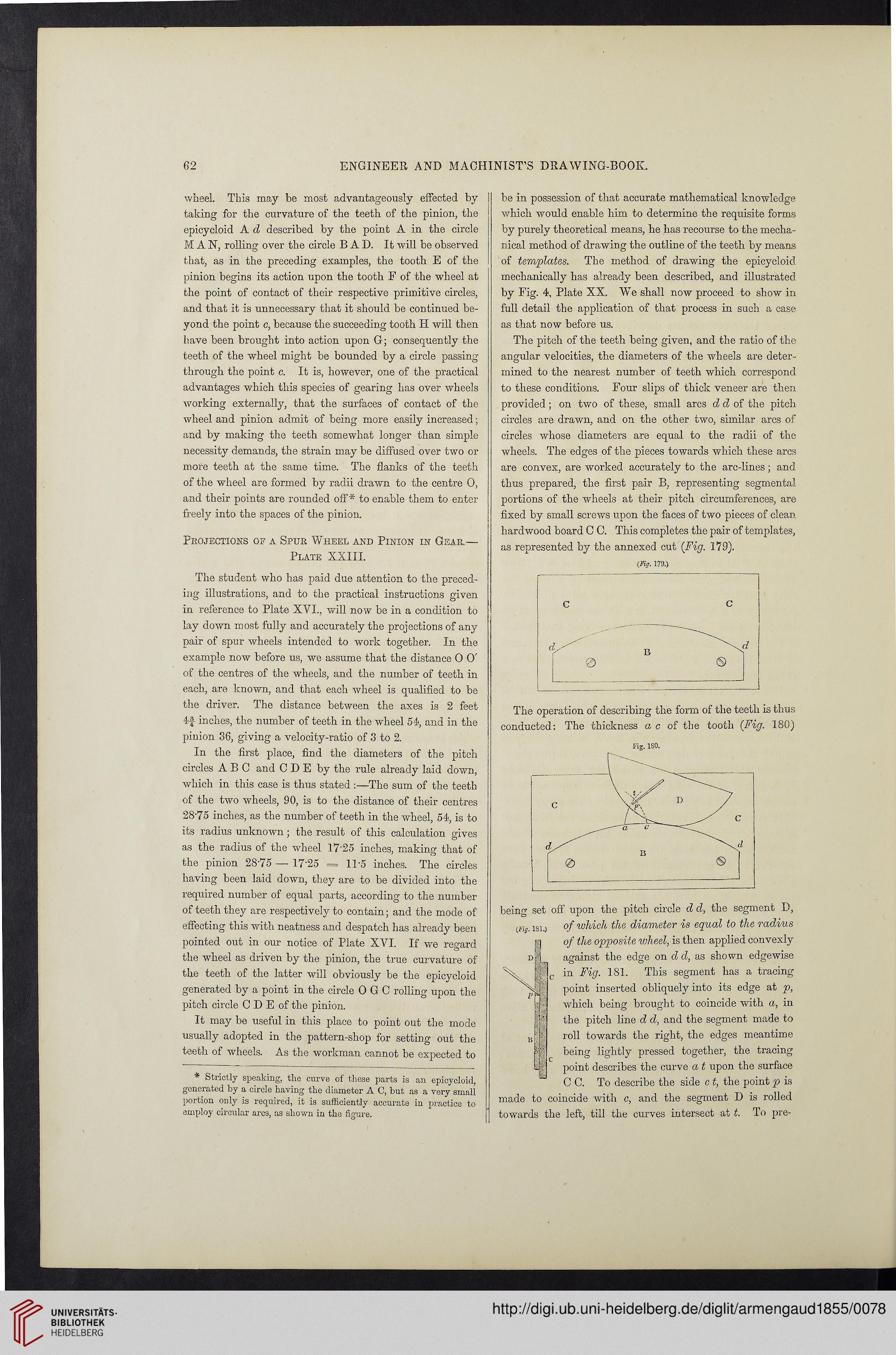
The operation of describing the form of the teeth is thus
conducted: The thickness ac of the tooth (Fig. 180)
lug. iso.
being set oft" upon the pitch circle d d, the segment D,
{Ftg 18l0 of which the diameter is equal to the radius
of the opposite wheel, is then applied convexly
against the edge on d, d, as shown edgewise
in Fig. 181. This segment has a tracing
point inserted obliquely into its edge at p,
which being brought to coincide with a, in
the pitch line d d, and the segment made to
roll towards the right, the edges meantime
being lightly pressed together, the tracing
point describes the curve a t upon the surface
C C. To describe the side c t, the point p is
made to coincide with c, and the segment D is rolled
towards the left, till the curves intersect at t. To pre-
ENGINEER AND MACHINIST’S DRAWING-BOOK.
wheel. This may be most advantageously effected by
taking for the curvature of the teeth of the pinion, the
epicycloid A d described by the point A in the circle
M A N, rolling over the circle BAD. It will be observed
that, as in the preceding examples, the tooth E of the
pinion begins its action upon the tooth F of the wheel at
the point of contact of their respective primitive circles,
and that it is unnecessary that it should be continued be-
yond the point c, because the succeeding tooth H will then
have been brought into action upon G; consequently the
teeth of the wheel might be bounded by a circle passing
through the point e. It is, however, one of the practical
advantages which this species of gearing has over wheels
working externally, that the surfaces of contact of the
wheel and pinion admit of being more easily increased;
and by making the teeth somewhat longer than simple
necessity demands, the strain may be diffused over two or
more teeth at the same time. The flanks of the teeth
of the wheel are formed by radii drawn to the centre 0,
and their points are rounded off* to enable them to enter
freely into the spaces of the pinion.
Projections of a Spur Wheel and Pinion in Gear.—
Plate XXIII.
The student who has paid due attention to the preced-
ing illustrations, and to the practical instructions given
in reference to Plate XVI., will now be in a condition to
lay down most fully and accurately the projections of any
pair of spur wheels intended to work together. In the
example now before us, we assume that the distance O 0'
of the centres of the wheels, and the number of teeth in
each, are known, and that each wheel is qualified to be
the driver. The distance between the axes is 2 feet
4f inches, the number of teeth in the wheel 54, and in the
pinion 36, giving a velocity-ratio of 3 to 2.
In the first place, find the diameters of the pitch
circles ABC and C D E by the rule already laid down,
which in this case is thus stated :—The sum of the teeth
of the two wheels, 90, is to the distance of their centres
2875 inches, as the number of teeth in the wheel, 54, is to
its radius unknown; the result of this calculation gives
as the radius of the wheel 17 25 inches, making that of
the pinion 2875 — 17-25 = 11-5 inches. The circles
having been laid down, they are to be divided into the
required number of equal parts, according to the number
of teeth they are respectively to contain; and the mode of
effecting this with neatness and despatch has already been
pointed out in our notice of Plate XVI. If we regard
the wheel as driven by the pinion, the true curvature of
the teeth of the latter will obviously be the epicycloid
generated by a point in the circle 0 G C rolling upon the
pitch circle C D E of the pinion.
It may be useful in this place to point out the mode
usually adopted in the pattern-shop for setting out the
teeth of wheels. As the workman cannot be expected to
* Strictly speaking, the curve of these parts is an epicycloid,
generated by a circle having the diameter A C, but as a very small
portion only is required, it is sufficiently accurate in practice to
employ circular arcs, as shown in the figure.
be in possession of that accurate mathematical knowledge
which would enable him to determine the requisite forms
by purely theoretical means, he has recourse to the mecha-
nical method of drawing the outline of the teeth by means
of templates. The method of drawing the epicycloid
mechanically has already been described, and illustrated
by Fig. 4, Plate XX. We shall now proceed to show in
full detail the application of that process in such a case
as that now before us.
The pitch of the teeth being given, and the ratio of the
angular velocities, the diameters of the wheels are deter-
mined to the nearest number of teeth which correspond
to these conditions. Four slips of thick veneer are then
provided; on two of these, small arcs d d of the pitch
circles are drawn, and on the other two, similar arcs of
circles whose diameters are equal to the radii of the
wheels. The edges of the pieces towards which these arcs
are convex, are worked accurately to the arc-lines; and
thus prepared, the first pair B. representing segmental
portions of the wheels at their pitch circumferences, are
fixed by small screws upon the faces of two pieces of clean
hardwood board C C. This completes the pair of templates,
as represented by the annexed cut (Fig. 179).
179.)
c c
0 0
The operation of describing the form of the teeth is thus
conducted: The thickness ac of the tooth (Fig. 180)
lug. iso.
being set oft" upon the pitch circle d d, the segment D,
{Ftg 18l0 of which the diameter is equal to the radius
of the opposite wheel, is then applied convexly
against the edge on d, d, as shown edgewise
in Fig. 181. This segment has a tracing
point inserted obliquely into its edge at p,
which being brought to coincide with a, in
the pitch line d d, and the segment made to
roll towards the right, the edges meantime
being lightly pressed together, the tracing
point describes the curve a t upon the surface
C C. To describe the side c t, the point p is
made to coincide with c, and the segment D is rolled
towards the left, till the curves intersect at t. To pre-