

DOI Seite / Zitierlink:
https://doi.org/10.11588/diglit.25888#0079


DRAWING OF MACHINERY.
G3
vent the segmental edges sliding upon each other during
the operation, they are sometimes rubbed with chalk or
ilour-rosin.
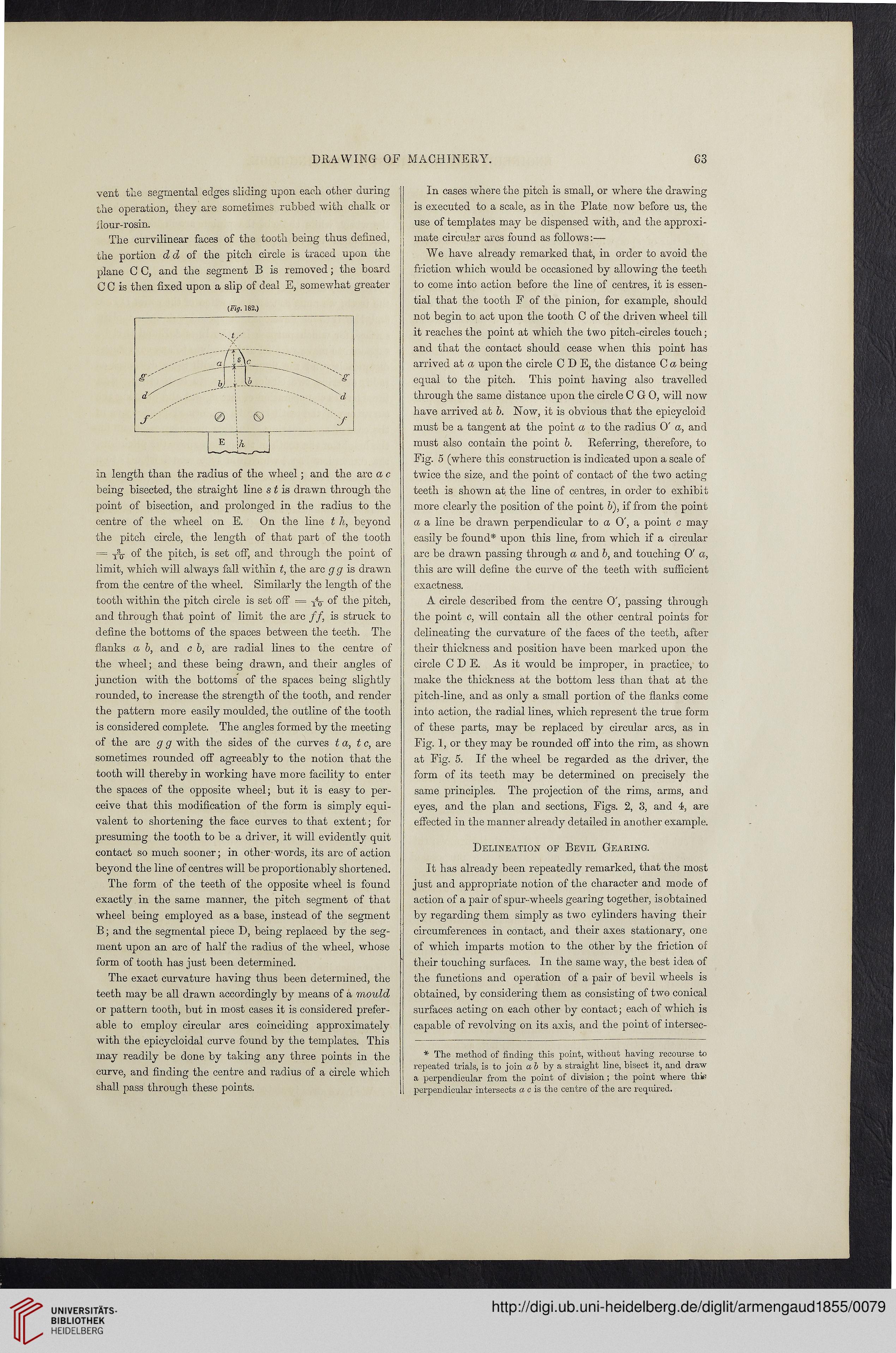
The curvilinear faces of the tooth being thus defined,
the portion dd of the pitch circle is traced upon the
plane C C, and the segment B is removed; the board
C C is then fixed upon a slip of deal E, somewhat greater
(Fig. 182.)
in length than the radius of the wheel; and the arc a c
being bisected, the straight line s t is drawn through the
point of bisection, and prolonged in the radius to the
centre of the wheel on E. On the line t h, beyond
the pitch circle, the length of that part of the tooth
= Yq- of the pitch, is set off, and through the point of
limit, which will always fall within t, the arc g g is drawn
from the centre of the wheel. Similarly the length of the
tooth within the pitch circle is set off = W of the pitch,
and through that point of limit the arc //, is struck to
define the bottoms of the spaces between the teeth. The
flanks a b, and c b, are radial lines to the centre of
the wheel; and these being drawn, and their angles of
junction with the bottoms of the spaces being slightly
rounded, to increase the strength of the tooth, and render
the pattern more easily moulded, the outline of the tooth
is considered complete. The angles formed by the meeting
of the arc g g with the sides of the curves t a, t c, are
sometimes rounded off agreeably to the notion that the
tooth will thereby in working have more facility to enter
the spaces of the opposite wheel; but it is easy to per-
ceive that this modification of the form is simply equi-
valent to shortening the face curves to that extent; for
presuming the tooth to be a driver, it will evidently quit
contact so much sooner; in other words, its arc of action
beyond the line of centres will be proportionably shortened.
The form of the teeth of the opposite wheel is found
exactly in the same manner, the pitch segment of that
wheel being employed as a base, instead of the segment
B; and the segmental piece D, being replaced by the seg-
ment upon an arc of half the radius of the wheel, whose
form of tooth has just been determined.
The exact curvature having thus been determined, the
teeth may be all drawn accordingly by means of a mould
or pattern tooth, but in most cases it is considered prefer-
able to employ circular arcs coinciding approximately
with the epicycloidal curve found by the templates. This
may readily be done by taking any three points in the
curve, and finding the centre and radius of a circle which
shall pass through these points.
In cases where the pitch is small, or where the drawing
is executed to a scale, as in the Plate now before us, the
use of templates may be dispensed with, and the approxi-
mate circular arcs found as follows:—
We have already remarked that, in order to avoid the
friction which would be occasioned by allowing the teeth
to come into action before the line of centres, it is essen-
tial that the tooth E of the pinion, for example, should
not begin to act upon the tooth C of the driven wheel till
it reaches the point at which the two pitch-circles touch;
and that the contact should cease when this point has
arrived at a upon the circle C D E, the distance C a being
equal to the pitch. This point having also travelled
through the same distance upon the circle C G 0, will now
have arrived at b. Now, it is obvious that the epicycloid
must be a tangent at the point a to the radius 0' a, and
must also contain the point b. Referring, therefore, to
Fig. 5 (where this construction is indicated upon a scale of
twice the size, and the point of contact of the two acting
teeth is shown at the line of centres, in order to exhibit
more clearly the position of the point 6), if from the point
a a line be drawn perpendicular to a O', a point c may
easily be found* upon this line, from which if a circular
arc be drawn passing through a and b, and touching O' a,
this arc will define the curve of the teeth with sufficient
exactness.
A circle described from the centre O', passing through
the point c, will contain all the other central points for
delineating the curvature of the faces of the teeth, after
their thickness and position have been marked upon the
circle C D E. As it would be improper, in practice, to
make the thickness at the bottom less than that at the
pitch-line, and as only a small portion of the flanks come
into action, the radial lines, which represent the true form
of these parts, may be replaced by circular arcs, as in
Fig. 1, or they may be rounded off into the rim, as shown
at Fig. 5. If the wheel be regarded as the driver, the
form of its teeth may be determined on precisely the
same principles. The projection of the rims, arms, and
eyes, and the plan and sections, Figs. 2, 3, and 4, are
effected in the manner already detailed in another example.
Delineation of Bevil Gearing.
It has already been repeatedly remarked, that the most
just and appropriate notion of the character and mode of
action of a pair of sp ur-wheels gearing together, is obtained
by regarding them simply as two cylinders having their
circumferences in contact, and their axes stationary, one
of which imparts motion to the other by the friction of
their touching surfaces. In the same way, the best idea of
the functions and operation of a pair of bevil wheels is
obtained, by considering them as consisting of two conical
surfaces acting on each other by contact; each of which is
capable of revolving on its axis, and the point of intersec-
* The method of finding this point, without having recourse to
repeated trials, is to join a & by a straight line, bisect it, and draw
a perpendicular from the point of division ; the point where thie
perpendicular intersects a c is the centre of the arc required.
G3
vent the segmental edges sliding upon each other during
the operation, they are sometimes rubbed with chalk or
ilour-rosin.
The curvilinear faces of the tooth being thus defined,
the portion dd of the pitch circle is traced upon the
plane C C, and the segment B is removed; the board
C C is then fixed upon a slip of deal E, somewhat greater
(Fig. 182.)
in length than the radius of the wheel; and the arc a c
being bisected, the straight line s t is drawn through the
point of bisection, and prolonged in the radius to the
centre of the wheel on E. On the line t h, beyond
the pitch circle, the length of that part of the tooth
= Yq- of the pitch, is set off, and through the point of
limit, which will always fall within t, the arc g g is drawn
from the centre of the wheel. Similarly the length of the
tooth within the pitch circle is set off = W of the pitch,
and through that point of limit the arc //, is struck to
define the bottoms of the spaces between the teeth. The
flanks a b, and c b, are radial lines to the centre of
the wheel; and these being drawn, and their angles of
junction with the bottoms of the spaces being slightly
rounded, to increase the strength of the tooth, and render
the pattern more easily moulded, the outline of the tooth
is considered complete. The angles formed by the meeting
of the arc g g with the sides of the curves t a, t c, are
sometimes rounded off agreeably to the notion that the
tooth will thereby in working have more facility to enter
the spaces of the opposite wheel; but it is easy to per-
ceive that this modification of the form is simply equi-
valent to shortening the face curves to that extent; for
presuming the tooth to be a driver, it will evidently quit
contact so much sooner; in other words, its arc of action
beyond the line of centres will be proportionably shortened.
The form of the teeth of the opposite wheel is found
exactly in the same manner, the pitch segment of that
wheel being employed as a base, instead of the segment
B; and the segmental piece D, being replaced by the seg-
ment upon an arc of half the radius of the wheel, whose
form of tooth has just been determined.
The exact curvature having thus been determined, the
teeth may be all drawn accordingly by means of a mould
or pattern tooth, but in most cases it is considered prefer-
able to employ circular arcs coinciding approximately
with the epicycloidal curve found by the templates. This
may readily be done by taking any three points in the
curve, and finding the centre and radius of a circle which
shall pass through these points.
In cases where the pitch is small, or where the drawing
is executed to a scale, as in the Plate now before us, the
use of templates may be dispensed with, and the approxi-
mate circular arcs found as follows:—
We have already remarked that, in order to avoid the
friction which would be occasioned by allowing the teeth
to come into action before the line of centres, it is essen-
tial that the tooth E of the pinion, for example, should
not begin to act upon the tooth C of the driven wheel till
it reaches the point at which the two pitch-circles touch;
and that the contact should cease when this point has
arrived at a upon the circle C D E, the distance C a being
equal to the pitch. This point having also travelled
through the same distance upon the circle C G 0, will now
have arrived at b. Now, it is obvious that the epicycloid
must be a tangent at the point a to the radius 0' a, and
must also contain the point b. Referring, therefore, to
Fig. 5 (where this construction is indicated upon a scale of
twice the size, and the point of contact of the two acting
teeth is shown at the line of centres, in order to exhibit
more clearly the position of the point 6), if from the point
a a line be drawn perpendicular to a O', a point c may
easily be found* upon this line, from which if a circular
arc be drawn passing through a and b, and touching O' a,
this arc will define the curve of the teeth with sufficient
exactness.
A circle described from the centre O', passing through
the point c, will contain all the other central points for
delineating the curvature of the faces of the teeth, after
their thickness and position have been marked upon the
circle C D E. As it would be improper, in practice, to
make the thickness at the bottom less than that at the
pitch-line, and as only a small portion of the flanks come
into action, the radial lines, which represent the true form
of these parts, may be replaced by circular arcs, as in
Fig. 1, or they may be rounded off into the rim, as shown
at Fig. 5. If the wheel be regarded as the driver, the
form of its teeth may be determined on precisely the
same principles. The projection of the rims, arms, and
eyes, and the plan and sections, Figs. 2, 3, and 4, are
effected in the manner already detailed in another example.
Delineation of Bevil Gearing.
It has already been repeatedly remarked, that the most
just and appropriate notion of the character and mode of
action of a pair of sp ur-wheels gearing together, is obtained
by regarding them simply as two cylinders having their
circumferences in contact, and their axes stationary, one
of which imparts motion to the other by the friction of
their touching surfaces. In the same way, the best idea of
the functions and operation of a pair of bevil wheels is
obtained, by considering them as consisting of two conical
surfaces acting on each other by contact; each of which is
capable of revolving on its axis, and the point of intersec-
* The method of finding this point, without having recourse to
repeated trials, is to join a & by a straight line, bisect it, and draw
a perpendicular from the point of division ; the point where thie
perpendicular intersects a c is the centre of the arc required.