

DOI Seite / Zitierlink:
https://doi.org/10.11588/diglit.25888#0126


110
ENGINEER AND MACHINIST’S DRAWING-BOOK.
as the axis is perpendicular to the picture, its vanishing
point will be the point of sight C'. Having drawn R C',
the perspective of the axis, find on it the centres of the
circles. Find first the diameter of the circle E G; through
l, the centre, draw l C, cutting the picture in l, and from l
raise a vertical line cutting the axis R C' in V the centre
sought. The radius l E has for its perspective the radius
V e, with which, from the perspective centre l, we describe
the circle e e, and so on for all the other circles, and
finally we circumscribe them by the elliptic curve.
This method is a little long, and has not all the pre-
cision which could be desired, for the two axes of the
ellipse have not first of all been determined, which would
simplify the operation; but this figure was necessary to
show that the union of all the circles contains all the
visible parts of the sphere, and forms an ellipse in the
picture; and, moreover, it was absolutely required for the
understanding of the following method, which is a conse-
quence of it, but which is much more simple and precise.
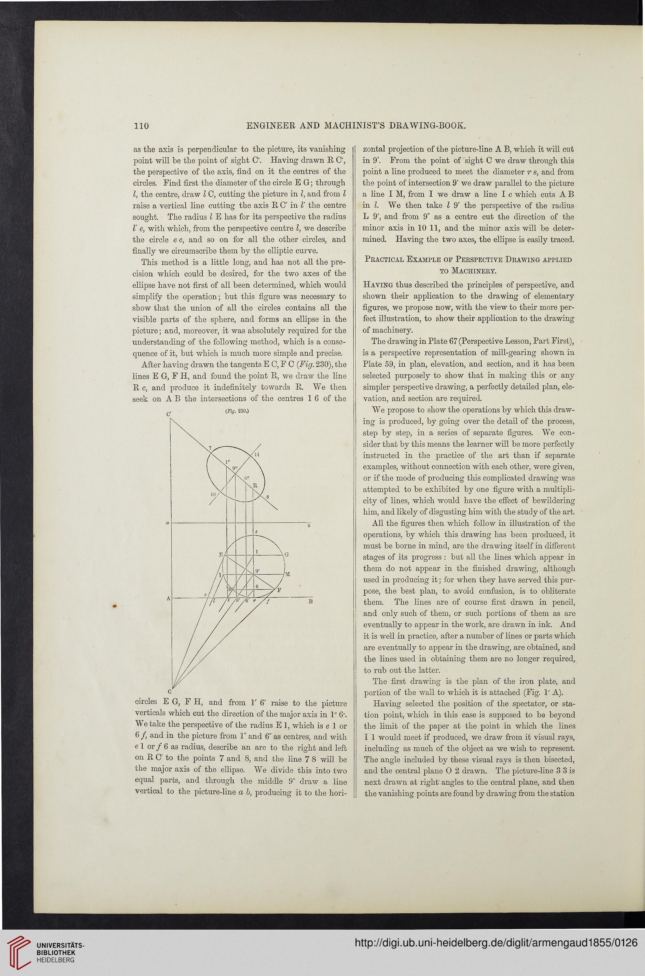
After having drawn the tangents E C, F C (Fig. 230), the
lines E G, F H, and found the point R, we draw the line
R c, and produce it indefinitely towards R. We then
seek on A B the intersections of the centres 1 6 of the
(Fig. 230.)
circles EG, F H, and from 1' 6' raise to the picture
verticals which cut the direction of the major axis in 1" 6".
We take the perspective of the radius E 1, which is e 1 or
6/, and in the picture from 1" and 6" as centres, and with
el or/ 6 as radius, describe an arc to the right and left
on R C to the points 7 and 8, and the line 7 8 will be
che major axis of the ellipse. We divide this into two
equal parts, and through the middle 9" draw a line
vertical to the picture-line a b, producing it to the hori-
zontal projection of the picture-line A B, which it will cut
in 9'. From the point of sight C we draw through this
point a line produced to meet the diameter r s, and from
the point of intersection 9' we draw parallel to the picture
a line I M, from I we draw a line I c which cuts A B
in l. We then take l 9' the perspective of the radius
L 9', and from 9" as a centre cut the direction of the
minor axis in 10 11, and the minor axis will be deter-
mined. Having the two axes, the ellipse is easily traced.
Practical Example of Perspective Drawing applied
to Machinery.
Having thus described the principles of perspective, and
shown their application to the drawing of elementary
figures, we propose now, with the view to their more per-
fect illustration, to show their application to the drawing
of machinery.
The drawing in Plate 67 (Perspective Lesson, Part First),
is a perspective representation of mill-gearing shown in
Plate 59, in plan, elevation, and section, and it has been
selected purposely to show that in making this or any
simpler perspective drawing, a perfectly detailed plan, ele-
vation, and section are required.
We propose to show the operations by which this draw-
ing is produced, by going over the detail of the process,
step by step, in a series of separate figures. We con-
sider that by this means the learner will be more perfectly
instructed in the practice of the art than if separate
examples, without connection with each other, were given,
or if the mode of producing this complicated drawing was
attempted to be exhibited by one figure with a multipli-
city of lines, which would have the effect of bewildering
him, and likely of disgusting him with the study of the art.
All the figures then which follow in illustration of the
operations, by which this drawing has been produced, it
must be borne in mind, are the drawing itself in different
stages of its progress : but all the lines which appear in
them do not appear in the finished drawing, although
used in producing it: for when they have served this pur-
pose, the best plan, to avoid confusion, is to obliterate
them. The lines are of course first drawn in pencil,
and only such of them, or such portions of them as are
eventually to appear in the work, are drawn in ink. And
it is well in practice, after a number of lines or parts which
are eventually to appear in the drawing, are obtained, and
the lines used in obtaining them are no longer required,
to rub out the latter.
The first drawing is the plan of the iron plate, and
portion of the wall to which it is attached (Fig. 1' A).
Having selected the position of the spectator, or sta-
tion point, which in this case is supposed to be beyond
the limit of the paper at the point in which the lines
I 1 would meet if produced, we (draw from it visual rays,
including as much of the object as we wish to represent.
The angle included by these visual rays is then bisected,
and the central plane 0 2 drawn. The picture-line 3 3 is
next drawn at right angles to the central plane, and then
the vanishing points are found by drawing from the station
ENGINEER AND MACHINIST’S DRAWING-BOOK.
as the axis is perpendicular to the picture, its vanishing
point will be the point of sight C'. Having drawn R C',
the perspective of the axis, find on it the centres of the
circles. Find first the diameter of the circle E G; through
l, the centre, draw l C, cutting the picture in l, and from l
raise a vertical line cutting the axis R C' in V the centre
sought. The radius l E has for its perspective the radius
V e, with which, from the perspective centre l, we describe
the circle e e, and so on for all the other circles, and
finally we circumscribe them by the elliptic curve.
This method is a little long, and has not all the pre-
cision which could be desired, for the two axes of the
ellipse have not first of all been determined, which would
simplify the operation; but this figure was necessary to
show that the union of all the circles contains all the
visible parts of the sphere, and forms an ellipse in the
picture; and, moreover, it was absolutely required for the
understanding of the following method, which is a conse-
quence of it, but which is much more simple and precise.
After having drawn the tangents E C, F C (Fig. 230), the
lines E G, F H, and found the point R, we draw the line
R c, and produce it indefinitely towards R. We then
seek on A B the intersections of the centres 1 6 of the
(Fig. 230.)
circles EG, F H, and from 1' 6' raise to the picture
verticals which cut the direction of the major axis in 1" 6".
We take the perspective of the radius E 1, which is e 1 or
6/, and in the picture from 1" and 6" as centres, and with
el or/ 6 as radius, describe an arc to the right and left
on R C to the points 7 and 8, and the line 7 8 will be
che major axis of the ellipse. We divide this into two
equal parts, and through the middle 9" draw a line
vertical to the picture-line a b, producing it to the hori-
zontal projection of the picture-line A B, which it will cut
in 9'. From the point of sight C we draw through this
point a line produced to meet the diameter r s, and from
the point of intersection 9' we draw parallel to the picture
a line I M, from I we draw a line I c which cuts A B
in l. We then take l 9' the perspective of the radius
L 9', and from 9" as a centre cut the direction of the
minor axis in 10 11, and the minor axis will be deter-
mined. Having the two axes, the ellipse is easily traced.
Practical Example of Perspective Drawing applied
to Machinery.
Having thus described the principles of perspective, and
shown their application to the drawing of elementary
figures, we propose now, with the view to their more per-
fect illustration, to show their application to the drawing
of machinery.
The drawing in Plate 67 (Perspective Lesson, Part First),
is a perspective representation of mill-gearing shown in
Plate 59, in plan, elevation, and section, and it has been
selected purposely to show that in making this or any
simpler perspective drawing, a perfectly detailed plan, ele-
vation, and section are required.
We propose to show the operations by which this draw-
ing is produced, by going over the detail of the process,
step by step, in a series of separate figures. We con-
sider that by this means the learner will be more perfectly
instructed in the practice of the art than if separate
examples, without connection with each other, were given,
or if the mode of producing this complicated drawing was
attempted to be exhibited by one figure with a multipli-
city of lines, which would have the effect of bewildering
him, and likely of disgusting him with the study of the art.
All the figures then which follow in illustration of the
operations, by which this drawing has been produced, it
must be borne in mind, are the drawing itself in different
stages of its progress : but all the lines which appear in
them do not appear in the finished drawing, although
used in producing it: for when they have served this pur-
pose, the best plan, to avoid confusion, is to obliterate
them. The lines are of course first drawn in pencil,
and only such of them, or such portions of them as are
eventually to appear in the work, are drawn in ink. And
it is well in practice, after a number of lines or parts which
are eventually to appear in the drawing, are obtained, and
the lines used in obtaining them are no longer required,
to rub out the latter.
The first drawing is the plan of the iron plate, and
portion of the wall to which it is attached (Fig. 1' A).
Having selected the position of the spectator, or sta-
tion point, which in this case is supposed to be beyond
the limit of the paper at the point in which the lines
I 1 would meet if produced, we (draw from it visual rays,
including as much of the object as we wish to represent.
The angle included by these visual rays is then bisected,
and the central plane 0 2 drawn. The picture-line 3 3 is
next drawn at right angles to the central plane, and then
the vanishing points are found by drawing from the station