

DOI Seite / Zitierlink:
https://doi.org/10.11588/diglit.25888#0130


114
ENGINEER AND MACHINIST’S DRAWING-BOOK.
ginning at the hither angle of the largest block on the
figure, and adding the minor parts. Eig. 236 shows the
interior of what may be considered a box or a building.
Fig. 237 requires no description.
° 1 (Fig. 236.)
The following figures show how lines which are not
o o
isometric may be obtained by the aid of those which are.
In Fig. 238, A is the half-plan of a pyramid with a square
base. By including it in an isometrical square, its projec-
tion is readily obtained.
Fig. 239 is an octagon, Fig. 240 a hexagon, and Fig. 241 a
pentagon. The projections are obtained by the intersec-
tions of their lines, or their lines produced with the sides
of the circumscribing square; and it may be observed by
these examples, that the projection of any line making any
angle whatever with the isometric lines, can be very easily
obtained. In the figures, all the lines of construction
arising from the various intersections are shown for
the sake of illustrations. But in practice it is easily to be
seen, that it is only necessary to obtain a few of the inter-
sections. As for example, in Fig. 239, the points ab ode f,
and in Fig. 240 the points abcdefgh.
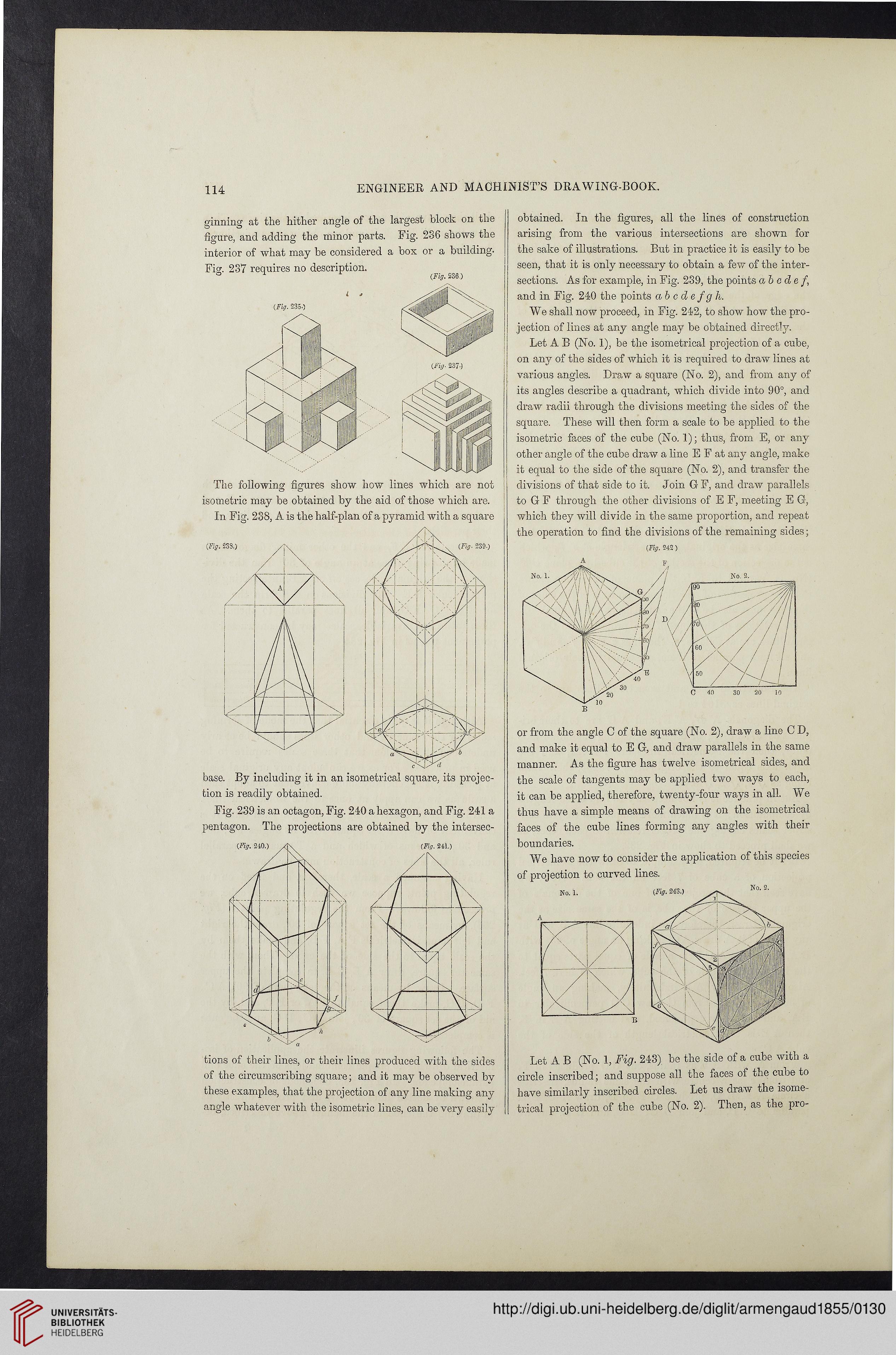
We shall now proceed, in Fig. 242, to show how the pro-
jection of lines at any angle may be obtained directly.
Let A B (No. 1), be the isometrical projection of a cube,
on any of the sides of which it is required to draw lines at
various angles. Draw a square (No. 2), and from any of
its angles describe a quadrant, which divide into 90°, and
draw radii through the divisions meeting the sides of the
square. These will then form a scale to be applied to the
isometric faces of the cube (No. 1); thus, from E, or any
other angle of the cube draw a line E F at any angle, make
it equal to the side of the square (No. 2), and transfer the
divisions of that side to it. Join G F, and draw parallels
to G F through the other divisions of E F, meeting E G,
which they will divide in the same proportion, and repeat
the operation to find the divisions of the remaining sides;
(Fig. 242)
or from the angle C of the square (No. 2), draw a line C D,
and make it equal to E G, and draw parallels in the same
manner. As the figure has twelve isometrical sides, and
the scale of tangents may be applied two ways to each,
it can be applied, therefore, twenty-four ways in all. We
thus have a simple means of drawing on the isometrical
faces of the cube lines forming any angles with their
boundaries.
We have now to consider the application of this species
of projection to curved lines.
Let A B (No. 1, Fig. 243) be the side of a cube with a
circle inscribed; and suppose all the faces of the cube to
have similarly inscribed circles. Let us draw the isome-
trical projection of the cube (No. 2). Then, as the pio-
ENGINEER AND MACHINIST’S DRAWING-BOOK.
ginning at the hither angle of the largest block on the
figure, and adding the minor parts. Eig. 236 shows the
interior of what may be considered a box or a building.
Fig. 237 requires no description.
° 1 (Fig. 236.)
The following figures show how lines which are not
o o
isometric may be obtained by the aid of those which are.
In Fig. 238, A is the half-plan of a pyramid with a square
base. By including it in an isometrical square, its projec-
tion is readily obtained.
Fig. 239 is an octagon, Fig. 240 a hexagon, and Fig. 241 a
pentagon. The projections are obtained by the intersec-
tions of their lines, or their lines produced with the sides
of the circumscribing square; and it may be observed by
these examples, that the projection of any line making any
angle whatever with the isometric lines, can be very easily
obtained. In the figures, all the lines of construction
arising from the various intersections are shown for
the sake of illustrations. But in practice it is easily to be
seen, that it is only necessary to obtain a few of the inter-
sections. As for example, in Fig. 239, the points ab ode f,
and in Fig. 240 the points abcdefgh.
We shall now proceed, in Fig. 242, to show how the pro-
jection of lines at any angle may be obtained directly.
Let A B (No. 1), be the isometrical projection of a cube,
on any of the sides of which it is required to draw lines at
various angles. Draw a square (No. 2), and from any of
its angles describe a quadrant, which divide into 90°, and
draw radii through the divisions meeting the sides of the
square. These will then form a scale to be applied to the
isometric faces of the cube (No. 1); thus, from E, or any
other angle of the cube draw a line E F at any angle, make
it equal to the side of the square (No. 2), and transfer the
divisions of that side to it. Join G F, and draw parallels
to G F through the other divisions of E F, meeting E G,
which they will divide in the same proportion, and repeat
the operation to find the divisions of the remaining sides;
(Fig. 242)
or from the angle C of the square (No. 2), draw a line C D,
and make it equal to E G, and draw parallels in the same
manner. As the figure has twelve isometrical sides, and
the scale of tangents may be applied two ways to each,
it can be applied, therefore, twenty-four ways in all. We
thus have a simple means of drawing on the isometrical
faces of the cube lines forming any angles with their
boundaries.
We have now to consider the application of this species
of projection to curved lines.
Let A B (No. 1, Fig. 243) be the side of a cube with a
circle inscribed; and suppose all the faces of the cube to
have similarly inscribed circles. Let us draw the isome-
trical projection of the cube (No. 2). Then, as the pio-