

DOI Seite / Zitierlink:
https://doi.org/10.11588/diglit.25888#0018


2
ENGINEER AND MACHINIST’S DRAWING-BOOK.
be measured is first taken as accurately as possible between
the points of the compasses, and the screw is then turned
until the dimension is obtained with positive exactness.
This instrument is useless unless it be of the very best
quality; it must work firmly and steadily; and the points
need to be exquisitely adjusted, exceedingly fine, and
well-tempered.
Instruction for using dividers, which are applied only
to measure and transfer distances and dimensions, may
appear superfluous; but there are a few simple directions
which may save the young draughtsman much perplexity
and loss of time. It is, of course, desirable to work the
compasses in such a manner that, when the dimension is
taken, it may suffer no disturbance in its transfer from the
scale to the drawing. In order to this, the instrument is
to be held by the head or joint, the forefinger resting on
the top of the joint, and the thumb and second finger on
either side. When held in this way, there is no pressure
except on the head and centre, and the dimension between
the points cannot be altered; but, if the instrument be
clumsily seized by a thumb on one leg, and two fingers
on the other, the pressure, in the act of transference, must
inevitably contract, in some small degree, the opening of
the compasses; and if the dimension has to be set off
several times, the probability is, that no two transfers will
be exactly the same. And, whilst it is all-important to
keep the dimension exact, it is also desirable to manipulate
in such a way, when setting off the same dimension a
number of times, that the point of position be never lost.
Persons unaccustomed to the use of compasses, are very
apt to turn them over and over in the same direction,
when laying down a number of equal measures, and this
necessitates a frequent change of the finger and thumb,
which direct the movement of the instrument; the con-
sequence is, either that the fixed leg is driven deep into
the drawing, or it loses position. Now, if the movement
be alternately above and below the line on which the dis-
tances are being set off, the compasses can be worked with
great freedom and delicacy, and without any liability to
shifting. If a straight line is drawn, and semicircles be
described alternately above and below the line, it will
show the path of the traversing foot. If the two move-
ments are tried, the superiority of the one recommended
will at once be discovered. The forefinger rests gently
on the head; and the thumb and second finger, without
changing from side to side, direct the movement for setting
off any number of times that may be required.
There is a third sort of dividers, named the Spring
Compasses, in which steadiness is combined with the
delicacy of adjustment of the Hair Compasses. The last-
named is liable to error, in consequence of the weakness
of the spring leg ; and without very careful handling, the
dimension, though taken with extreme exactness, cannot
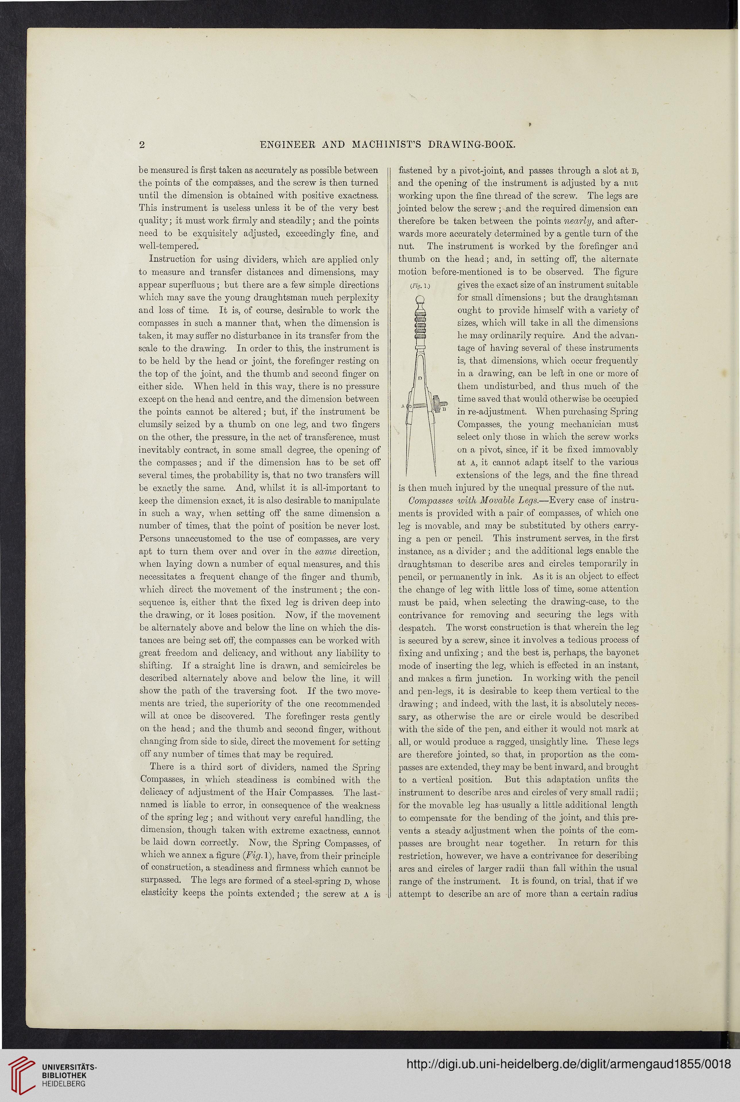
be laid down correctly. Now, the Spring Compasses, of
which we annex a figure (Fig. 1), have, from their principle
of construction, a steadiness and firmness which cannot be
surpassed. The legs are formed of a steel-spring d, whose
elasticity keeps the points extended; the screw at A is
fastened by a pivot-joint, and passes through a slot at B,
and the opening of the instrument is adjusted by a nut-
working upon the fine thread of the screw. The legs are
jointed below the screw ; and the required dimension can
therefore be taken between the points nearly, and after-
wards more accurately determined by a gentle turn of the
nut. The instrument is worked by the forefinger and
thumb on the head; and, in setting off, the alternate
motion before-mentioned is to be observed. The figure
(Fig. i.) gives the exact size of an instrument suitable
for small dimensions ; but the draughts]nan
ought to provide himself with a variety of
sizes, which will take in all the dimensions
he may ordinarily require. And the advan-
tage of having several of these instruments
is, that dimensions, which occur frequently
in a drawing, can be left in one or more of
them undisturbed, and thus much of the
time saved that would otherwise be occupied
in re-adjustment. When purchasing Spring
Compasses, the young mechanician must
select only those in which the screw works
on a pivot, since, if it be fixed immovably
at A, it cannot adapt itself to the various
extensions of the legs, and the fine thread
is then much injured by the unequal pressure of the nut.
Compasses with Movable Legs.—Every case of instru-
ments is provided with a pair of compasses, of which one
leg is movable, and may be substituted by others carry-
ing a pen or pencil. This instrument serves, in the first
instance, as a divider ; and the additional legs enable the
draughtsman to describe arcs and circles temporarily in
pencil, or permanently in ink. As it is an object to effect
the change of leg with little loss of time, some attention
must be paid, when selecting the drawing-case, to the
contrivance for removing and securing the legs with
despatch. The worst construction is that wherein the leg
is secured by a screw, since it involves a tedious process of
fixing and unfixing ; and the best is, perhaps, the bayonet
mode of inserting the leg, which is effected in an instant,
and makes a firm junction. In working with the pencil
and pen-legs, it is desirable to keep them vertical to the
drawing ; and indeed, with the last, it is absolutely neces-
sary, as otherwise the arc or circle would be described
with the side of the pen, and either it would not mark at
all, or would produce a ragged, unsightly line. These legs
are therefore jointed, so that, in proportion as the com-
passes are extended, they may be bent inward, and brought
to a vertical position. But this adaptation unfits the
instrument to describe arcs and circles of very small radii;
for the movable leg has usually a little additional length
to compensate for the bending of the joint, and this pre-
vents a steady adjustment when the points of the com-
passes are brought near together. In return for this
restriction, however, we have a contrivance for describing
arcs and circles of larger radii than fall within the usual
range of the instrument. It is found, on trial, that if we
attempt to describe an arc of more than a certain radius
ENGINEER AND MACHINIST’S DRAWING-BOOK.
be measured is first taken as accurately as possible between
the points of the compasses, and the screw is then turned
until the dimension is obtained with positive exactness.
This instrument is useless unless it be of the very best
quality; it must work firmly and steadily; and the points
need to be exquisitely adjusted, exceedingly fine, and
well-tempered.
Instruction for using dividers, which are applied only
to measure and transfer distances and dimensions, may
appear superfluous; but there are a few simple directions
which may save the young draughtsman much perplexity
and loss of time. It is, of course, desirable to work the
compasses in such a manner that, when the dimension is
taken, it may suffer no disturbance in its transfer from the
scale to the drawing. In order to this, the instrument is
to be held by the head or joint, the forefinger resting on
the top of the joint, and the thumb and second finger on
either side. When held in this way, there is no pressure
except on the head and centre, and the dimension between
the points cannot be altered; but, if the instrument be
clumsily seized by a thumb on one leg, and two fingers
on the other, the pressure, in the act of transference, must
inevitably contract, in some small degree, the opening of
the compasses; and if the dimension has to be set off
several times, the probability is, that no two transfers will
be exactly the same. And, whilst it is all-important to
keep the dimension exact, it is also desirable to manipulate
in such a way, when setting off the same dimension a
number of times, that the point of position be never lost.
Persons unaccustomed to the use of compasses, are very
apt to turn them over and over in the same direction,
when laying down a number of equal measures, and this
necessitates a frequent change of the finger and thumb,
which direct the movement of the instrument; the con-
sequence is, either that the fixed leg is driven deep into
the drawing, or it loses position. Now, if the movement
be alternately above and below the line on which the dis-
tances are being set off, the compasses can be worked with
great freedom and delicacy, and without any liability to
shifting. If a straight line is drawn, and semicircles be
described alternately above and below the line, it will
show the path of the traversing foot. If the two move-
ments are tried, the superiority of the one recommended
will at once be discovered. The forefinger rests gently
on the head; and the thumb and second finger, without
changing from side to side, direct the movement for setting
off any number of times that may be required.
There is a third sort of dividers, named the Spring
Compasses, in which steadiness is combined with the
delicacy of adjustment of the Hair Compasses. The last-
named is liable to error, in consequence of the weakness
of the spring leg ; and without very careful handling, the
dimension, though taken with extreme exactness, cannot
be laid down correctly. Now, the Spring Compasses, of
which we annex a figure (Fig. 1), have, from their principle
of construction, a steadiness and firmness which cannot be
surpassed. The legs are formed of a steel-spring d, whose
elasticity keeps the points extended; the screw at A is
fastened by a pivot-joint, and passes through a slot at B,
and the opening of the instrument is adjusted by a nut-
working upon the fine thread of the screw. The legs are
jointed below the screw ; and the required dimension can
therefore be taken between the points nearly, and after-
wards more accurately determined by a gentle turn of the
nut. The instrument is worked by the forefinger and
thumb on the head; and, in setting off, the alternate
motion before-mentioned is to be observed. The figure
(Fig. i.) gives the exact size of an instrument suitable
for small dimensions ; but the draughts]nan
ought to provide himself with a variety of
sizes, which will take in all the dimensions
he may ordinarily require. And the advan-
tage of having several of these instruments
is, that dimensions, which occur frequently
in a drawing, can be left in one or more of
them undisturbed, and thus much of the
time saved that would otherwise be occupied
in re-adjustment. When purchasing Spring
Compasses, the young mechanician must
select only those in which the screw works
on a pivot, since, if it be fixed immovably
at A, it cannot adapt itself to the various
extensions of the legs, and the fine thread
is then much injured by the unequal pressure of the nut.
Compasses with Movable Legs.—Every case of instru-
ments is provided with a pair of compasses, of which one
leg is movable, and may be substituted by others carry-
ing a pen or pencil. This instrument serves, in the first
instance, as a divider ; and the additional legs enable the
draughtsman to describe arcs and circles temporarily in
pencil, or permanently in ink. As it is an object to effect
the change of leg with little loss of time, some attention
must be paid, when selecting the drawing-case, to the
contrivance for removing and securing the legs with
despatch. The worst construction is that wherein the leg
is secured by a screw, since it involves a tedious process of
fixing and unfixing ; and the best is, perhaps, the bayonet
mode of inserting the leg, which is effected in an instant,
and makes a firm junction. In working with the pencil
and pen-legs, it is desirable to keep them vertical to the
drawing ; and indeed, with the last, it is absolutely neces-
sary, as otherwise the arc or circle would be described
with the side of the pen, and either it would not mark at
all, or would produce a ragged, unsightly line. These legs
are therefore jointed, so that, in proportion as the com-
passes are extended, they may be bent inward, and brought
to a vertical position. But this adaptation unfits the
instrument to describe arcs and circles of very small radii;
for the movable leg has usually a little additional length
to compensate for the bending of the joint, and this pre-
vents a steady adjustment when the points of the com-
passes are brought near together. In return for this
restriction, however, we have a contrivance for describing
arcs and circles of larger radii than fall within the usual
range of the instrument. It is found, on trial, that if we
attempt to describe an arc of more than a certain radius