

DOI Seite / Zitierlink:
https://doi.org/10.11588/diglit.25888#0049


GEOMETRICAL CONSTRUCTIONS—DRAWING OF ELEMENTARY FORMS.
S3
tions of ellipses. It is employed in striking out vaults,
and stone-bridges.
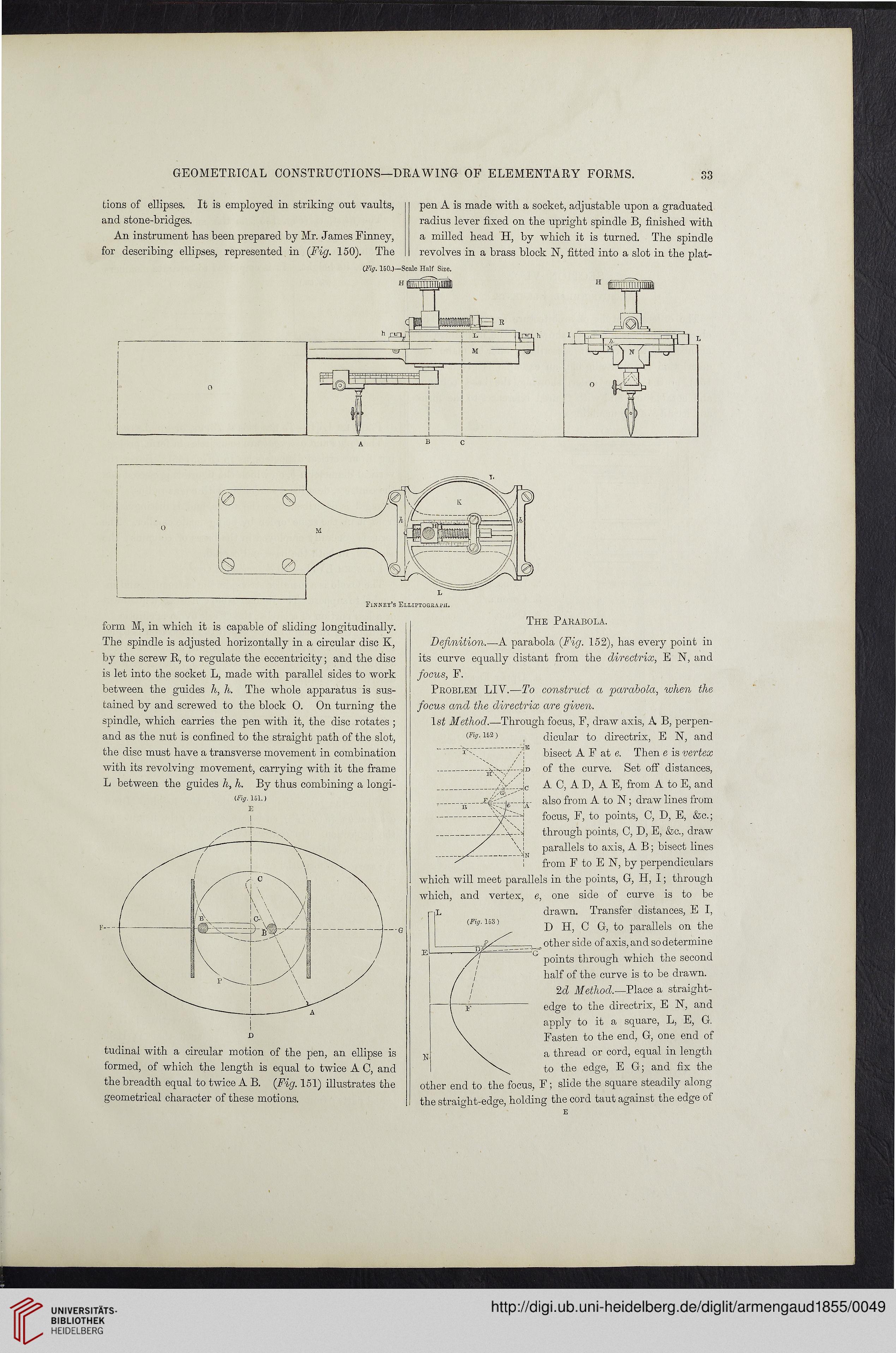
An instrument has been prepared by Mr. James Finney,
for describing ellipses, represented in (Fig. 150). The
pen A is made with a socket, adjustable upon a graduated
radius lever fixed on the upright spindle B, finished with
a milled head H, by which it is turned. The spindle
revolves in a brass block N, fitted into a slot in the plat-
CFig. 150.)—Scale Half Size.
Finney’s ELLiPTOGB.AfH.
form M, in which it is capable of sliding longitudinally.
The spindle is adjusted horizontally in a circular disc K,
by the screw R, to regulate the eccentricity; and the disc
is let into the socket L, made with parallel sides to work
between the guides h, h. The whole apparatus is sus-
tained by and screwed to the block 0. On turning the
spindle, which carries the pen with it, the disc rotates ;
and as the nut is confined to the straight path of the slot,
the disc must have a transverse movement in combination
with its revolving movement, carrying with it the frame
L between the guides h, h. By thus combining a longi-
(Fig. 151.)
E
tudinai with a circular motion of the pen, an ellipse is
formed, of which the length is equal to twice A C, and
the breadth equal to twice A B. (Fig. 151) illustrates the
geometrical character of these motions.
The Parabola.
'TIE
-AT>
\
Definition.—A parabola (Fig. 152), has every point in
its curve equally distant from the directrix, E N, and
focus, F.
Problem LIY.—To construct a parabola, when the
focus and the directrix are given.
1st Method.—Through focus, F, draw axis, A B, perpen-
(Fig. 152) ( dicular to directrix, E N, and
bisect A F at e. Then e is vertex
of the curve. Set off distances,
Jc A C, A D, A E, from A to E, and
i also from A to N; draw lines from
-Ya---A focus, F, to points, C, D, E, &c.;
-j through points, C, D, E, &c., draw
parallels to axis, A B; bisect lines
from F to E N, by perpendiculars
which will meet parallels in the points, G, H, I; through
which, and vertex, e, one side of curve is to be
drawn. Transfer distances, E I,
D H, C G, to parallels on the
other side of axis, and so determine
points through which the second
half of the curve is to be drawn.
2d Method.—Place a straight-
edge to the directrix, E N, and
apply to it a square, L, E, G.
Fasten to the end, G, one end of
a thread or cord, equal in length
to the edge, E G; and fix the
other end to the focus, F; slide the square steadily along
the straight-edge, holding the cord taut against the edge of
S3
tions of ellipses. It is employed in striking out vaults,
and stone-bridges.
An instrument has been prepared by Mr. James Finney,
for describing ellipses, represented in (Fig. 150). The
pen A is made with a socket, adjustable upon a graduated
radius lever fixed on the upright spindle B, finished with
a milled head H, by which it is turned. The spindle
revolves in a brass block N, fitted into a slot in the plat-
CFig. 150.)—Scale Half Size.
Finney’s ELLiPTOGB.AfH.
form M, in which it is capable of sliding longitudinally.
The spindle is adjusted horizontally in a circular disc K,
by the screw R, to regulate the eccentricity; and the disc
is let into the socket L, made with parallel sides to work
between the guides h, h. The whole apparatus is sus-
tained by and screwed to the block 0. On turning the
spindle, which carries the pen with it, the disc rotates ;
and as the nut is confined to the straight path of the slot,
the disc must have a transverse movement in combination
with its revolving movement, carrying with it the frame
L between the guides h, h. By thus combining a longi-
(Fig. 151.)
E
tudinai with a circular motion of the pen, an ellipse is
formed, of which the length is equal to twice A C, and
the breadth equal to twice A B. (Fig. 151) illustrates the
geometrical character of these motions.
The Parabola.
'TIE
-AT>
\
Definition.—A parabola (Fig. 152), has every point in
its curve equally distant from the directrix, E N, and
focus, F.
Problem LIY.—To construct a parabola, when the
focus and the directrix are given.
1st Method.—Through focus, F, draw axis, A B, perpen-
(Fig. 152) ( dicular to directrix, E N, and
bisect A F at e. Then e is vertex
of the curve. Set off distances,
Jc A C, A D, A E, from A to E, and
i also from A to N; draw lines from
-Ya---A focus, F, to points, C, D, E, &c.;
-j through points, C, D, E, &c., draw
parallels to axis, A B; bisect lines
from F to E N, by perpendiculars
which will meet parallels in the points, G, H, I; through
which, and vertex, e, one side of curve is to be
drawn. Transfer distances, E I,
D H, C G, to parallels on the
other side of axis, and so determine
points through which the second
half of the curve is to be drawn.
2d Method.—Place a straight-
edge to the directrix, E N, and
apply to it a square, L, E, G.
Fasten to the end, G, one end of
a thread or cord, equal in length
to the edge, E G; and fix the
other end to the focus, F; slide the square steadily along
the straight-edge, holding the cord taut against the edge of