

DOI Seite / Zitierlink:
https://doi.org/10.11588/diglit.25888#0051


GEOMETRICAL CONSTRUCTIONS—DRAWING OF ELEMENTARY FORMS.
35
division in E F, and from K draw lines to meet those
others successively. The intersections so found are
points in the curve, which may be traced accordingly.
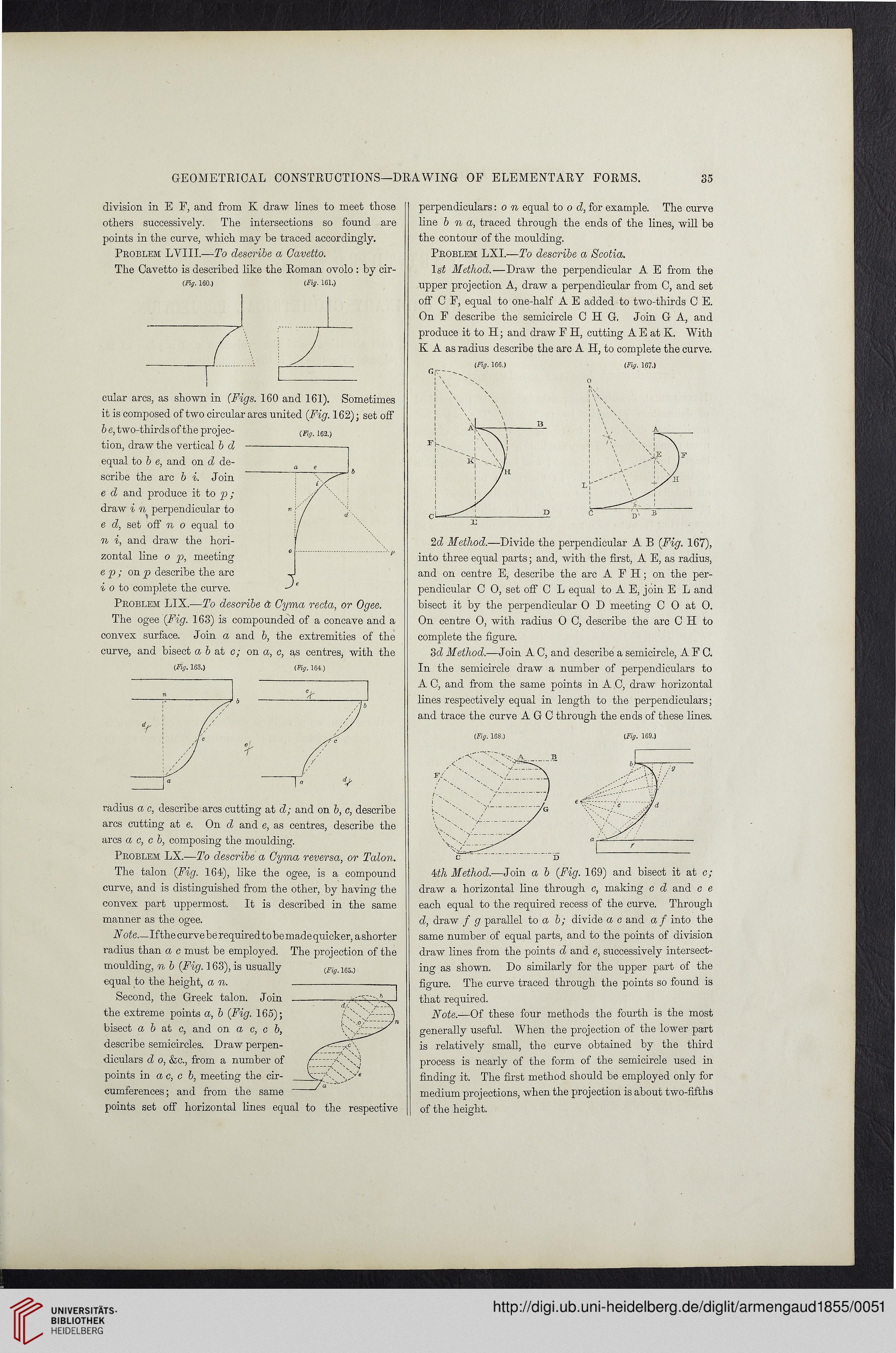
Problem LYIII.—To describe a Gavetto.
The Cavetto is described like the Roman ovolo : by cir-
(Fig. 160.) (Fig- 161.)
cular arcs, as shown in (Figs. 160 and 161). Sometimes
it is composed of two circular arcs united (Fig. 162); set off
b e, two-thirds of the projec-
tion, draw the vertical b d
equal to b e, and on d de-
scribe the arc b i. Join
e d and produce it to p ;
draw i % perpendicular to
e d, set off n o equal to
n i, and draw the hori-
zontal line o p, meeting
e p ; on p describe the arc
i o to complete the curve.
Problem LIX.—To describe & Cyma recta, or Ogee.
The ogee (Fig. 163) is compounded of a concave and a
conves surface. Join a and b, the extremities of the
curve, and bisect a b at c; on a, c, as centres, with the
(Fig. 163.) (Fig. 164.)
radius a c, describe arcs cutting at d; and on b, c, describe
arcs cutting at e. On d and e, as centres, describe the
arcs a c, c b, composing the moulding.
Problem LX.—To describe a Cyma reversa, or Talon.
The talon (Fig. 164), like the ogee, is a compound
curve, and is distinguished from the other, by having the
convex part uppermost. It is described in the same
manner as the ogee.
N ote—If the curve be required to be made quicker, a shorter
radius than a c must be employed. The projection of the
moulding, n b (Fig. 163), is usually
equal to the height, a n.
Second, the Greek talon. Join
the extreme points a, b (Fig. 165);
bisect a b at c, and on a c, c b,
describe semicircles. Draw perpen-
diculars d o, &c., from a number of
points in a c, c b, meeting the cir-
cumferences ; and from the same
points set off horizontal lines equal to the respective
perpendiculars: o n equal to o d, for example. The curve
line b n a, traced through the ends of the lines, will be
the contour of the moulding.
Problem LXI.—To describe a Scotia.
ls£ Method.—Draw the perpendicular A E from the
upper projection A, draw a perpendicular from C, and set
off C F, equal to one-half A E added to two-thirds C E.
On F describe the semicircle C H G, Join G A, and
produce it to H; and draw F H, cutting A E at K. With
K A as radius describe the arc A H, to complete the curve.
2d Method.—Divide the perpendicular A B (Fig. 167),
into three equal parts; and, with the first, A E, as radius,
and on centre E, describe the arc A FH; on the per-
pendicular C 0, set off C L equal to A E, join E L and
bisect it by the perpendicular O D meeting C 0 at 0.
On centre 0, with radius 0 C, describe the arc C H to
complete the figure.
3 d Method.—Join A C, and describe a semicircle, AFC.
In the semicircle draw a number of perpendiculars to
A C, and from the same points in A C, draw horizontal
lines respectively equal in length to the perpendiculars;
and trace the curve A G C through the ends of these lines.
(Fig. 168.) (Fig. 169.)
4th Method.—Join a b (Fig. 169) and bisect it at c;
draw a horizontal line through c, making c d and c e
each equal to the required recess of the curve. Through
d, draw f g parallel to a- b; divide a c and a f into the
same number of equal parts, and to the points of division
draw lines from the points d and e, successively intersect-
ing as shown. Do similarly for the upper paid of the
figure. The curve traced through the points so found is
that required.
Note.—Of these four methods the fourth is the most
generally useful. When the projection of the lower part
is relatively small, the curve obtained by the third
process is nearly of the form of the semicircle used in
finding it. The first method should be employed only for
medium projections, when the projection is about two-fifths
of the height.
(Fig. 162.)
35
division in E F, and from K draw lines to meet those
others successively. The intersections so found are
points in the curve, which may be traced accordingly.
Problem LYIII.—To describe a Gavetto.
The Cavetto is described like the Roman ovolo : by cir-
(Fig. 160.) (Fig- 161.)
cular arcs, as shown in (Figs. 160 and 161). Sometimes
it is composed of two circular arcs united (Fig. 162); set off
b e, two-thirds of the projec-
tion, draw the vertical b d
equal to b e, and on d de-
scribe the arc b i. Join
e d and produce it to p ;
draw i % perpendicular to
e d, set off n o equal to
n i, and draw the hori-
zontal line o p, meeting
e p ; on p describe the arc
i o to complete the curve.
Problem LIX.—To describe & Cyma recta, or Ogee.
The ogee (Fig. 163) is compounded of a concave and a
conves surface. Join a and b, the extremities of the
curve, and bisect a b at c; on a, c, as centres, with the
(Fig. 163.) (Fig. 164.)
radius a c, describe arcs cutting at d; and on b, c, describe
arcs cutting at e. On d and e, as centres, describe the
arcs a c, c b, composing the moulding.
Problem LX.—To describe a Cyma reversa, or Talon.
The talon (Fig. 164), like the ogee, is a compound
curve, and is distinguished from the other, by having the
convex part uppermost. It is described in the same
manner as the ogee.
N ote—If the curve be required to be made quicker, a shorter
radius than a c must be employed. The projection of the
moulding, n b (Fig. 163), is usually
equal to the height, a n.
Second, the Greek talon. Join
the extreme points a, b (Fig. 165);
bisect a b at c, and on a c, c b,
describe semicircles. Draw perpen-
diculars d o, &c., from a number of
points in a c, c b, meeting the cir-
cumferences ; and from the same
points set off horizontal lines equal to the respective
perpendiculars: o n equal to o d, for example. The curve
line b n a, traced through the ends of the lines, will be
the contour of the moulding.
Problem LXI.—To describe a Scotia.
ls£ Method.—Draw the perpendicular A E from the
upper projection A, draw a perpendicular from C, and set
off C F, equal to one-half A E added to two-thirds C E.
On F describe the semicircle C H G, Join G A, and
produce it to H; and draw F H, cutting A E at K. With
K A as radius describe the arc A H, to complete the curve.
2d Method.—Divide the perpendicular A B (Fig. 167),
into three equal parts; and, with the first, A E, as radius,
and on centre E, describe the arc A FH; on the per-
pendicular C 0, set off C L equal to A E, join E L and
bisect it by the perpendicular O D meeting C 0 at 0.
On centre 0, with radius 0 C, describe the arc C H to
complete the figure.
3 d Method.—Join A C, and describe a semicircle, AFC.
In the semicircle draw a number of perpendiculars to
A C, and from the same points in A C, draw horizontal
lines respectively equal in length to the perpendiculars;
and trace the curve A G C through the ends of these lines.
(Fig. 168.) (Fig. 169.)
4th Method.—Join a b (Fig. 169) and bisect it at c;
draw a horizontal line through c, making c d and c e
each equal to the required recess of the curve. Through
d, draw f g parallel to a- b; divide a c and a f into the
same number of equal parts, and to the points of division
draw lines from the points d and e, successively intersect-
ing as shown. Do similarly for the upper paid of the
figure. The curve traced through the points so found is
that required.
Note.—Of these four methods the fourth is the most
generally useful. When the projection of the lower part
is relatively small, the curve obtained by the third
process is nearly of the form of the semicircle used in
finding it. The first method should be employed only for
medium projections, when the projection is about two-fifths
of the height.
(Fig. 162.)