

DOI Page / Citation link:
https://doi.org/10.11588/diglit.25888#0025


CONSTRUCTION AND USE OF DRAWING INSTRUMENTS.
9
With the line of lines we operate on any given line that
will come within the opening of the sector ; and with the
line of chords we can work with any radius of similar ex-
tent. This last is constructed by making the lateral dis-
tance of the chord of 60 degrees, which is radius, equal in
length to the line of lines. All the intermediate degrees
between 1 and 60, are then set off laterally from the centre,
on both rulers, by taking on the line of lines a measure
equal to twice the natural sine of half the angle. Thus, for
the chord of 80 degrees, refer to SherwiiTs Tables, or to
others of equal authority, and find the natural sine of 15 de-
grees, which is 2588190, when radius is 10,000,000, and
the double of this sine is 5176380. Now the line of lines
as radius is equal to 100, in place of 10,000,000, and the
measure of the double sine must therefore be taken from
it in two places of figures, instead of seven. We see at
once that the length of the chord is between 51 and 52 on
the line of lines. Take in the compasses, as nearly as
possible, 51, and three-fourths, and this measured from the
centre on the line of chords, will give the chord of 80 de-
grees. The young draughtsman ought to exercise himself
and test his sector by this and similar operations ; for it is
equally important that he understand the structure of his
scale, and be able to ascertain that the various lines of his
sector have a due relation to each other.
The line of chords is principally used to protract and
measure angles.
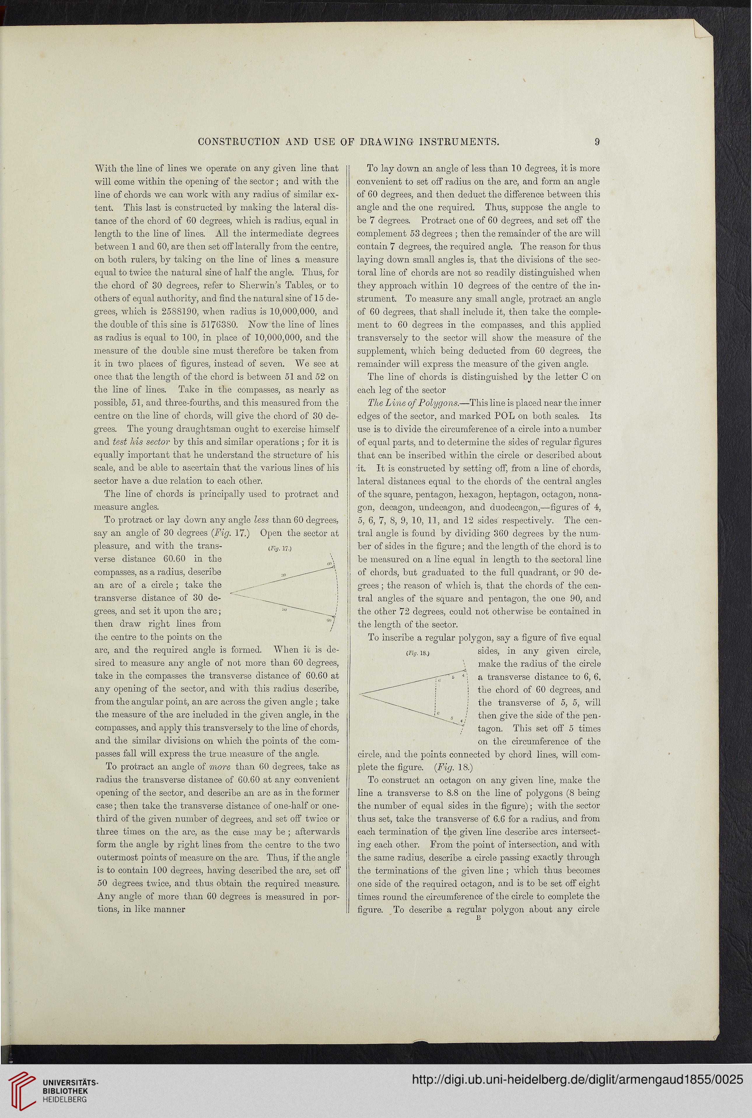
To protract or lay down any angle less than 60 degrees,
say an angle of 30 degrees (Fig. 17.) Open the sector at
pleasure, and with the trans-
verse distance 60.60 in the
compasses, as a radius, describe
an arc of a circle ; take the
transverse distance of 30 de-
grees, and set it upon the arc;
then draw right lines from
the centre to the points on the
arc, and the required angle is formed. When it is de-
sired to measure any angle of not more than 60 degrees,
take in the compasses the transverse distance of 60.60 at
any opening of the sector, and with this radius describe,
from the angular point, an arc across the given angle ; take
the measure of the arc included in the given angle, in the
compasses, and apply this transversely to the line of chords,
and the similar divisions on which the points of the com-
passes fall will express the true measure of the angle.
To protract an angle of more than 60 degrees, take as
radius the transverse distance of 60.60 at any convenient
opening of the sector, and describe an arc as in the former
case; then take the transverse distance of one-half or one-
third of the given number of degrees, and set off twice or
three times on the arc, as the case may be ; afterwards
form the angle by right lines from the centre to the two
outermost points of measure on the arc. Thus, if the angle
is to contain 100 degrees, having described the arc, set off
50 degrees twice, and thus obtain the required measure.
Any angle of more than 60 degrees is measured in por-
tions, in like manner
To lay down an angle of less than 10 degrees, it is more
convenient to set off radius on the arc, and form an angle
of 60 degrees, and then deduct the difference between this
angle and the one required. Thus, suppose the angle to
be 7 degrees. Protract one of 60 degrees, and set off the
complement 53 degrees ; then the remainder of the arc will
contain 7 degrees, the required angle. The reason for thus
laying down small angles is, that the divisions of the sec-
toral line of chords are not so readily distinguished when
they approach within 10 degrees of the centre of the in-
strument. To measure any small angle, protract an angle
of 60 degrees, that shall include it, then take the comple-
ment to 60 degrees in the compasses, and this applied
transversely to the sector will show the measure of the
supplement, which being deducted from 60 degrees, the
remainder will express the measure of the given angle.
The line of chords is distinguished by the letter C on
each leg of the sector
The Line of Polygons.—This line is placed near the inner
edges of the sector, and marked POL on both scales. Its
use is to divide the circumference of a circle into a number
of equal parts, and to determine the sides of regular figures
that can be inscribed within the circle or described about
it. It is constructed by setting off, from a line of chords,
lateral distances equal to the chords of the central angles
of the square, pentagon, hexagon, heptagon, octagon, nona-
gon, decagon, undecagon, and duodecagon,—figures of 4,
5, 6, 7, 8, 9, 10, 11, and 12 sides respectively. The cen-
tral angle is found by dividing 360 degrees by the num-
ber of sides in the figure; and the length of the chord is to
be measured on a line equal in length to the sectoral line
of chords, but graduated to the full quadrant, or 90 de-
grees ; the reason of which is, that the chords of the cen-
tral angles of the square and pentagon, the one 90, and
the other 72 degrees, could not otherwise be contained in
the length of the sector.
To inscribe a regular polygon, say a figure of five equal
(Fi/j. is.) sides, in any given circle,
make the radius of the circle
; a transverse distance to 6, 6,
! the chord of 60 degrees, and
: the transverse of 5, 5, will
/ then give the side of the pen-
tagon. This set off 5 times
on the circumference of the
circle, and the points connected by chord lines, will com-
plete the figure. (Fig. 18.)
To construct an octagon on any given line, make the
line a transverse to 8.8 on the line of polygons (8 being
the number of equal sides in the figure); with the sector
thus set, take the transverse of 6.6 for a radius, and from
each termination of the given line describe arcs intersect-
ing each other. From the point of intersection, and with
the same radius, describe a circle passing exactly through
the terminations of the given line ; which thus becomes
one side of the required octagon, and is to be set off eight
times round the circumference of the circle to complete the
figure. To describe a regular polygon about any circle
13
(Fig. 17.)
9
With the line of lines we operate on any given line that
will come within the opening of the sector ; and with the
line of chords we can work with any radius of similar ex-
tent. This last is constructed by making the lateral dis-
tance of the chord of 60 degrees, which is radius, equal in
length to the line of lines. All the intermediate degrees
between 1 and 60, are then set off laterally from the centre,
on both rulers, by taking on the line of lines a measure
equal to twice the natural sine of half the angle. Thus, for
the chord of 80 degrees, refer to SherwiiTs Tables, or to
others of equal authority, and find the natural sine of 15 de-
grees, which is 2588190, when radius is 10,000,000, and
the double of this sine is 5176380. Now the line of lines
as radius is equal to 100, in place of 10,000,000, and the
measure of the double sine must therefore be taken from
it in two places of figures, instead of seven. We see at
once that the length of the chord is between 51 and 52 on
the line of lines. Take in the compasses, as nearly as
possible, 51, and three-fourths, and this measured from the
centre on the line of chords, will give the chord of 80 de-
grees. The young draughtsman ought to exercise himself
and test his sector by this and similar operations ; for it is
equally important that he understand the structure of his
scale, and be able to ascertain that the various lines of his
sector have a due relation to each other.
The line of chords is principally used to protract and
measure angles.
To protract or lay down any angle less than 60 degrees,
say an angle of 30 degrees (Fig. 17.) Open the sector at
pleasure, and with the trans-
verse distance 60.60 in the
compasses, as a radius, describe
an arc of a circle ; take the
transverse distance of 30 de-
grees, and set it upon the arc;
then draw right lines from
the centre to the points on the
arc, and the required angle is formed. When it is de-
sired to measure any angle of not more than 60 degrees,
take in the compasses the transverse distance of 60.60 at
any opening of the sector, and with this radius describe,
from the angular point, an arc across the given angle ; take
the measure of the arc included in the given angle, in the
compasses, and apply this transversely to the line of chords,
and the similar divisions on which the points of the com-
passes fall will express the true measure of the angle.
To protract an angle of more than 60 degrees, take as
radius the transverse distance of 60.60 at any convenient
opening of the sector, and describe an arc as in the former
case; then take the transverse distance of one-half or one-
third of the given number of degrees, and set off twice or
three times on the arc, as the case may be ; afterwards
form the angle by right lines from the centre to the two
outermost points of measure on the arc. Thus, if the angle
is to contain 100 degrees, having described the arc, set off
50 degrees twice, and thus obtain the required measure.
Any angle of more than 60 degrees is measured in por-
tions, in like manner
To lay down an angle of less than 10 degrees, it is more
convenient to set off radius on the arc, and form an angle
of 60 degrees, and then deduct the difference between this
angle and the one required. Thus, suppose the angle to
be 7 degrees. Protract one of 60 degrees, and set off the
complement 53 degrees ; then the remainder of the arc will
contain 7 degrees, the required angle. The reason for thus
laying down small angles is, that the divisions of the sec-
toral line of chords are not so readily distinguished when
they approach within 10 degrees of the centre of the in-
strument. To measure any small angle, protract an angle
of 60 degrees, that shall include it, then take the comple-
ment to 60 degrees in the compasses, and this applied
transversely to the sector will show the measure of the
supplement, which being deducted from 60 degrees, the
remainder will express the measure of the given angle.
The line of chords is distinguished by the letter C on
each leg of the sector
The Line of Polygons.—This line is placed near the inner
edges of the sector, and marked POL on both scales. Its
use is to divide the circumference of a circle into a number
of equal parts, and to determine the sides of regular figures
that can be inscribed within the circle or described about
it. It is constructed by setting off, from a line of chords,
lateral distances equal to the chords of the central angles
of the square, pentagon, hexagon, heptagon, octagon, nona-
gon, decagon, undecagon, and duodecagon,—figures of 4,
5, 6, 7, 8, 9, 10, 11, and 12 sides respectively. The cen-
tral angle is found by dividing 360 degrees by the num-
ber of sides in the figure; and the length of the chord is to
be measured on a line equal in length to the sectoral line
of chords, but graduated to the full quadrant, or 90 de-
grees ; the reason of which is, that the chords of the cen-
tral angles of the square and pentagon, the one 90, and
the other 72 degrees, could not otherwise be contained in
the length of the sector.
To inscribe a regular polygon, say a figure of five equal
(Fi/j. is.) sides, in any given circle,
make the radius of the circle
; a transverse distance to 6, 6,
! the chord of 60 degrees, and
: the transverse of 5, 5, will
/ then give the side of the pen-
tagon. This set off 5 times
on the circumference of the
circle, and the points connected by chord lines, will com-
plete the figure. (Fig. 18.)
To construct an octagon on any given line, make the
line a transverse to 8.8 on the line of polygons (8 being
the number of equal sides in the figure); with the sector
thus set, take the transverse of 6.6 for a radius, and from
each termination of the given line describe arcs intersect-
ing each other. From the point of intersection, and with
the same radius, describe a circle passing exactly through
the terminations of the given line ; which thus becomes
one side of the required octagon, and is to be set off eight
times round the circumference of the circle to complete the
figure. To describe a regular polygon about any circle
13
(Fig. 17.)