

DOI Artikel:
Dywan, Tomasz: Od „szkoły berlińskiej” do secesji: przyczynek do architektury miejskich zakładów przemysłowych Lwowa w latach 1858–1914
DOI Seite / Zitierlink:https://doi.org/10.11588/diglit.51255#0237


0 o
Drawing 12. Plan of the gro-
und floor, cross-sections
and view of the elevation
of the carburized water gas
plant, according to the 1905
design. Drawing based on
the designs: dało, file 2, de-
scription 1, case 2101, f. 122.
Key to the building’s plan:
1 - instrument room; 2 - ma-
chinę room ; 3 - toilets;
4 - locker room and bath for
the workers; 5 - pumping
station ; 6 - steam boiler
room
-» see p. 194
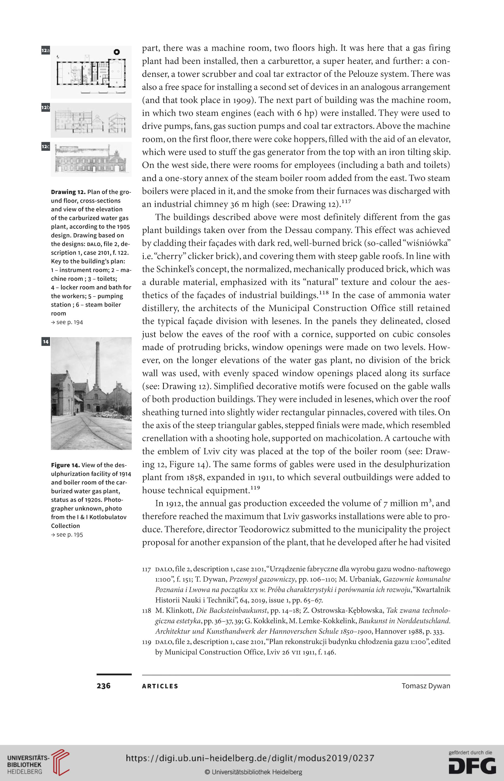
Figurę 14. View of the des-
ulphurization facility of 1914
and boiler room of the car-
burized water gas plant,
status as of 192OS. Photo-
grapher unknown, photo
from the I & I Kotlobulatov
Collection
-> see p. 195
236
part, there was a machinę room, two floors high. It was here that a gas firing
plant had been installed, then a carburettor, a super heater, and further: a con-
denser, a tower scrubber and coal tar extractor of the Pelouze system. There was
also a free space for installing a second set of devices in an analogous arrangement
(and that took place in 1909). The next part of building was the machinę room,
in which two steam engines (each with 6 hp) were installed. They were used to
drive pumps, fans, gas suction pumps and coal tar extractors. Above the machinę
room, on the first floor, there were coke hoppers, filled with the aid of an elevator,
which were used to stuff the gas generator from the top with an iron tilting skip.
On the west side, there were rooms for employees (including a bath and toilets)
and a one-story annex of the steam boiler room added from the east. Two steam
boilers were placed in it, and the smoke from their furnaces was discharged with
an industrial chimney 36 m high (see: Drawing 12).117
The buildings described above were most definitely different from the gas
plant buildings taken over from the Dessau company. This effect was achieved
by cladding their faęades with dark red, well-burned brick (so-called “wiśniówka”
i.e. “cherry” clicker brick), and covering them with steep gable roofs. In linę with
the Schinkels concept, the normalized, mechanically produced brick, which was
a durable materiał, emphasized with its “natural” texture and colour the aes-
thetics of the faęades of industrial buildings.118 In the case of ammonia water
distillery, the architects of the Municipal Construction Office still retained
the typical faęade division with lesenes. In the panels they delineated, closed
just below the eaves of the roof with a cornice, supported on cubic consoles
madę of protruding bricks, window openings were madę on two levels. How-
ever, on the longer elevations of the water gas plant, no division of the brick
wali was used, with evenly spaced window openings placed along its surface
(see: Drawing 12). Simplified decorative motifs were focused on the gable walls
of both production buildings. They were included in lesenes, which over the roof
sheathing turned into slightly wider rectangular pinnacles, covered with tiles. On
the axis of the steep triangular gables, stepped finials were madę, which resembled
crenellation with a shooting hole, supported on machicolation. A cartouche with
the emblem of Lviv city was placed at the top of the boiler room (see: Draw-
ing 12, Figurę 14). The same forms of gables were used in the desulphurization
plant from 1858, expanded in 1911, to which several outbuildings were added to
house technical eąuipment.119
In 1912, the annual gas production exceeded the volume of 7 million m3, and
therefore reached the maximum that Lviv gasworks installations were able to pro-
duce. Therefore, director Teodorowicz submitted to the municipality the project
proposal for another expansion of the plant, that he developed after he had visited
117 dało, file 2, description 1, case 2101,“Urządzenie fabryczne dla wyrobu gazu wodno-naftowego
1:100”, f. 151; T. Dywan, Przemysł gazowniczy, pp. 106-110; M. Urbaniak, Gazownie komunalne
Poznania i Lwowa na początku xx w. Próba charakterystyki i porównania ich rozwoju, “Kwartalnik
Historii Nauki i Techniki”, 64, 2019, issue 1, pp. 65-67.
118 M. Klinkott, Die Backsteinbaukunst, pp. 14-18; Z. Ostrowska-Kębłowska, Tak zwana technolo-
giczna estetyka, pp. 36-37,39; G. Kokkelink, M. Lemke-Kokkelink, Baukunst in Norddeutschland.
Architektur und Kunsthandwerk der Hannoverschen Schule 1850-1900, Hannover 1988, p. 333.
119 dało, file 2, description 1, case 2101,“Plan rekonstrukcji budynku chłodzenia gazu 1:100”, edited
by Municipal Construction Office, Lviv 26 vn 1911, f. 146.
ARTICLES
Tomasz Dywan
Drawing 12. Plan of the gro-
und floor, cross-sections
and view of the elevation
of the carburized water gas
plant, according to the 1905
design. Drawing based on
the designs: dało, file 2, de-
scription 1, case 2101, f. 122.
Key to the building’s plan:
1 - instrument room; 2 - ma-
chinę room ; 3 - toilets;
4 - locker room and bath for
the workers; 5 - pumping
station ; 6 - steam boiler
room
-» see p. 194
Figurę 14. View of the des-
ulphurization facility of 1914
and boiler room of the car-
burized water gas plant,
status as of 192OS. Photo-
grapher unknown, photo
from the I & I Kotlobulatov
Collection
-> see p. 195
236
part, there was a machinę room, two floors high. It was here that a gas firing
plant had been installed, then a carburettor, a super heater, and further: a con-
denser, a tower scrubber and coal tar extractor of the Pelouze system. There was
also a free space for installing a second set of devices in an analogous arrangement
(and that took place in 1909). The next part of building was the machinę room,
in which two steam engines (each with 6 hp) were installed. They were used to
drive pumps, fans, gas suction pumps and coal tar extractors. Above the machinę
room, on the first floor, there were coke hoppers, filled with the aid of an elevator,
which were used to stuff the gas generator from the top with an iron tilting skip.
On the west side, there were rooms for employees (including a bath and toilets)
and a one-story annex of the steam boiler room added from the east. Two steam
boilers were placed in it, and the smoke from their furnaces was discharged with
an industrial chimney 36 m high (see: Drawing 12).117
The buildings described above were most definitely different from the gas
plant buildings taken over from the Dessau company. This effect was achieved
by cladding their faęades with dark red, well-burned brick (so-called “wiśniówka”
i.e. “cherry” clicker brick), and covering them with steep gable roofs. In linę with
the Schinkels concept, the normalized, mechanically produced brick, which was
a durable materiał, emphasized with its “natural” texture and colour the aes-
thetics of the faęades of industrial buildings.118 In the case of ammonia water
distillery, the architects of the Municipal Construction Office still retained
the typical faęade division with lesenes. In the panels they delineated, closed
just below the eaves of the roof with a cornice, supported on cubic consoles
madę of protruding bricks, window openings were madę on two levels. How-
ever, on the longer elevations of the water gas plant, no division of the brick
wali was used, with evenly spaced window openings placed along its surface
(see: Drawing 12). Simplified decorative motifs were focused on the gable walls
of both production buildings. They were included in lesenes, which over the roof
sheathing turned into slightly wider rectangular pinnacles, covered with tiles. On
the axis of the steep triangular gables, stepped finials were madę, which resembled
crenellation with a shooting hole, supported on machicolation. A cartouche with
the emblem of Lviv city was placed at the top of the boiler room (see: Draw-
ing 12, Figurę 14). The same forms of gables were used in the desulphurization
plant from 1858, expanded in 1911, to which several outbuildings were added to
house technical eąuipment.119
In 1912, the annual gas production exceeded the volume of 7 million m3, and
therefore reached the maximum that Lviv gasworks installations were able to pro-
duce. Therefore, director Teodorowicz submitted to the municipality the project
proposal for another expansion of the plant, that he developed after he had visited
117 dało, file 2, description 1, case 2101,“Urządzenie fabryczne dla wyrobu gazu wodno-naftowego
1:100”, f. 151; T. Dywan, Przemysł gazowniczy, pp. 106-110; M. Urbaniak, Gazownie komunalne
Poznania i Lwowa na początku xx w. Próba charakterystyki i porównania ich rozwoju, “Kwartalnik
Historii Nauki i Techniki”, 64, 2019, issue 1, pp. 65-67.
118 M. Klinkott, Die Backsteinbaukunst, pp. 14-18; Z. Ostrowska-Kębłowska, Tak zwana technolo-
giczna estetyka, pp. 36-37,39; G. Kokkelink, M. Lemke-Kokkelink, Baukunst in Norddeutschland.
Architektur und Kunsthandwerk der Hannoverschen Schule 1850-1900, Hannover 1988, p. 333.
119 dało, file 2, description 1, case 2101,“Plan rekonstrukcji budynku chłodzenia gazu 1:100”, edited
by Municipal Construction Office, Lviv 26 vn 1911, f. 146.
ARTICLES
Tomasz Dywan